Q170226E01.pdf - 第72页
SERVICE MANUAL RH5 3.0−1 3 ダミー (Section のレベル 1) 3.0 ダミー (Section のレベル 2)
RH5
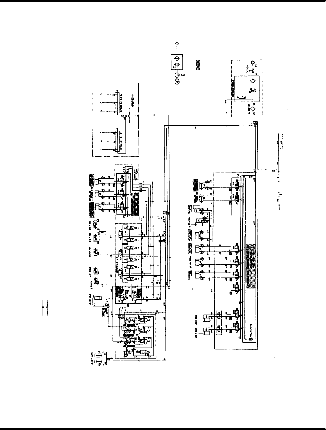
2.12 Pneumatic Circuit Diagram
SERVICE MANUAL
2.12−2
DA3SEC−82−110−A0
2.12.2 Pneumatic Circuit Diagram (NM−8245A/B/C)
(A) Insertion pusher regulator for high pressure
(B) Insertion pusher regulator for low pressure
(C) Regulator for insertion chuck
Indicate the direction of air (supply)
Indicate the direction of air (exhaust)
Insertion
pusher
Cut waste
drop
pusher
Transfer
chuck
Insertion
chuck
Guide
chuck
Cutter
return
Feed
lock
Rod swivel
lock
Cutter rod
cylinder
Concentrated lubrication unit
To anvil body
To anvil body
To guide pin
rod
To anvil body
To anvil body
To guide pin
rod
Air pump
Vacuum unit
Anvil (Dust cover
tube joint)
Guide pin
select (3)
Guide pin
select (2)
Pushout
unit
return
Walking
beam
return
Unloader
up/down
Loader
up/down
PCB
stopper
Feed
return
Anvil
swivel
lock
Walking
beam
up/dow
n
Option
Option
: Parts different
form RHIII

SERVICE MANUAL
RH5
3.0−1
3ダミー(Sectionのレベル1)
3.0ダミー(Sectionのレベル2)

RH5
SERVICE MANUAL
3.0−2
DA3SEC−11−000−B0
DA3SEC−11−000−B0
Sentence No.
3. INSTALLATION
This chapter includes general procedures of machine installation.
Beware that some descriptions in this chapter may not apply to the actual
machine depending on the specification.
x Be sure to read “Safety Precautions” in chapter 1 carefully.