Q170226E01.pdf - 第339页
RH5 8.4 AC Servomotor Drivers SERVICE MANUAL 8.4−2 DA3SEC−85−480−A0 Status Indication Mode When this mode is selected using the digital operator , the condition of the SGD SERVOP ACK is indicated with bits and codes as s…
8.4 AC Servomotor Drivers
SERVICE MANUAL
RH5
8.4−1
DA3SEC−85−480−A0
8.4 AC Servomotor Drivers
DA3SEC−85−480−A0
Sentence No.
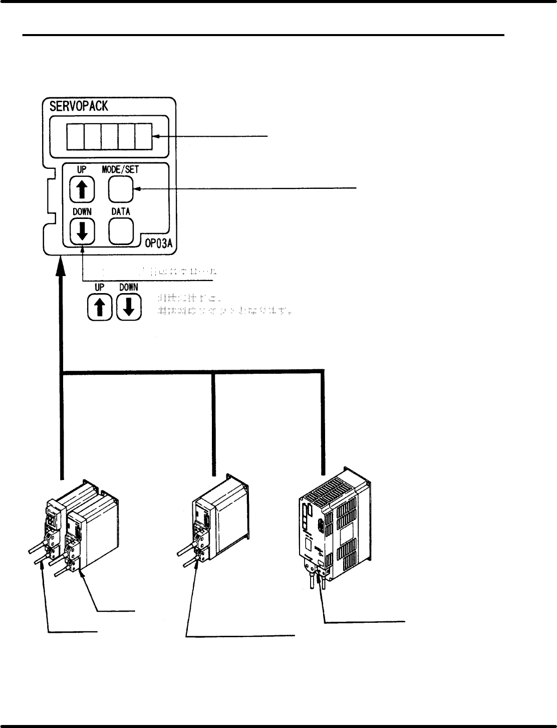
8.4.1 X/Y/Z (40−, 62−feeder) and H (Camshaft) Axis Driver
Digital Operator
Panel display
Mode select key
Status indication mode/Setting mode
For Y axis
For X axis
For Z axis (40−, 62−feeder)
H axis (Camshaft)
Press these keys simultaneously to
reset troubles.
Panel indication scroll keys
RH5
8.4 AC Servomotor Drivers
SERVICE MANUAL
8.4−2
DA3SEC−85−480−A0
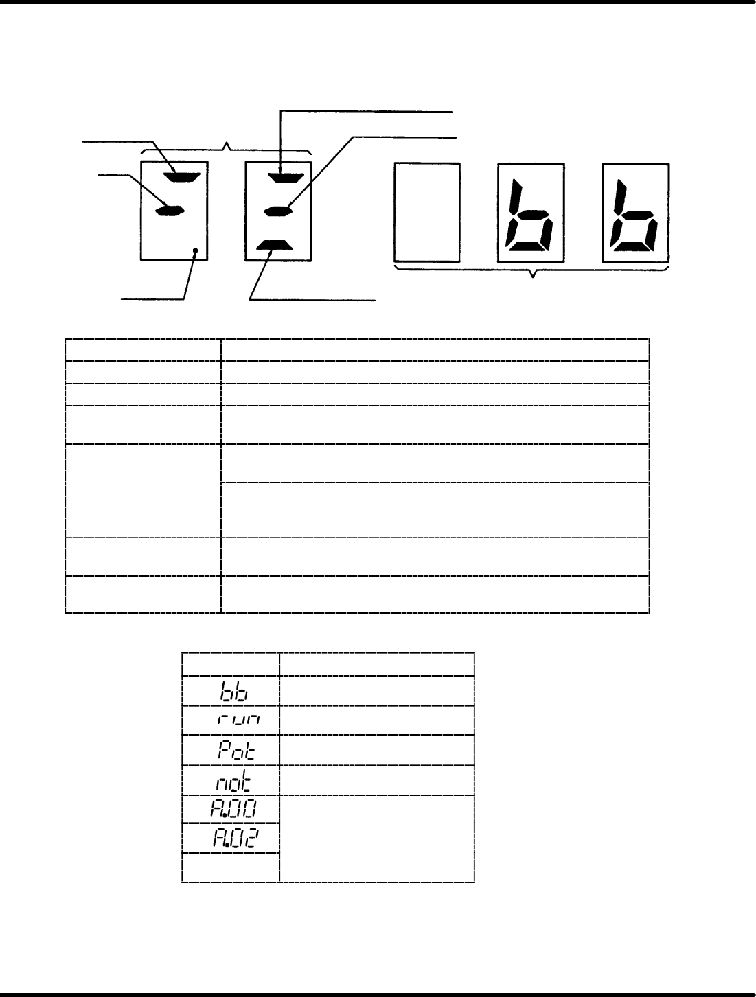
Status Indication Mode
When this mode is selected using the digital operator, the condition of the SGD SERVOPACK is
indicated with bits and codes as shown below.
Panel Display
Speed
reference
Bit data
BB
Power ON
TGON or current limit detection
Speed reference input
Torque reference input
Code
Bit Data Contents
Bit Data
Contents
Power ON Lights up when power is turned ON.
BB Lights up with base block and goes out when servo is turned ON.
Speed coincidence Lights up when the motor rotating speed reaches internal speed
reference.
TGON Lights up when the motor rotating speed exceeds TGON level
(standard setting is 20 r/min).
Current limit detection
Lights up when torque reference reaches the torque limit value.
(TGON or current limit detection is displayed according to bit 4 of
user constant Cn−01.)
Speed reference input Lights up if 1% or more speed reference of the maximum speed was
input.
Torque reference input Lights up if 10% or more torque reference of the rated torque was
input.
Codes and Status
Code Status
Base block
Running
Forward turn inhibited
Reverse turn inhibited
Alarm status
See
“
Error
Display
S
ee
“E
rror
Di
sp
l
ay
Confirmation with Digital
Operator
”
(page
53 3)
:
Operator” (page 5.3−3.).
8.4 AC Servomotor Drivers
SERVICE MANUAL
RH5
8.4−3
DA3SEC−85−480−A0
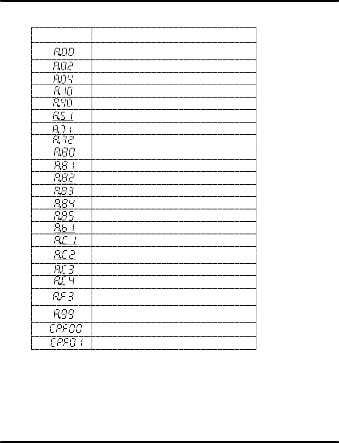
Error Display Confirmation with Digital Operator
Error Display with Digital Operator and Traceback Data
Digital Operator
(Traceback Data)
Detection
Absolute encoder data error (Only when absolute encoder
is used.)
Parameter breakdown
Parameter setting error
Overcurrent (or heatsink overheat)
Overvoltage
Overspeed (Detected at 110% of max. speed)
Overload (Momentary overload)
Overload (Continuous overload)
Encoder error (Only when absolute encoder is used.)
Encoder backup alarm *1
Encoder check sum error *1
Encoder battery error *1
Encoder absolute error *1
Encoder overspeed *1
Reference input read error
Overrun (Motor or encoder miswiring)
Phase detection error (Only when incremental encoder is
used.)
PA−, PB−phase disconnection of PG signal line
PC−phase disconnection of PG signal line
Momentary power loss alarm (Detected when power is
turned ON again during power holding time.)
Not applicable to alarm
Alarm reset Power ON (Only for traceback data)
Digital operator transmission error 1 *2
digital operator transmission error 2 *2
*1 Only when 12−bit absolute encoder is used.
*2 The following indications are digital operator errors. Not detected as traceback data.
=CHECK=
Use the digital operator attached to the Z−axis driver when checking X and Y axes.