Q170226E01.pdf - 第206页
− Measuring in progress − − Measuring completed − 5.32 Setting Offset V alues SERVICE MANUAL RH5 5.32−1 1 DA3SEC−83−9Q0−A0 6. Select Automatic Camera Offset Measuring. x Press F2 (C OFFSET). 7. Select the measuring direc…
RH5
5.32 Setting Offset Values
SERVICE MANUAL
5.32−10
DA3SEC−83−9Q0−A0
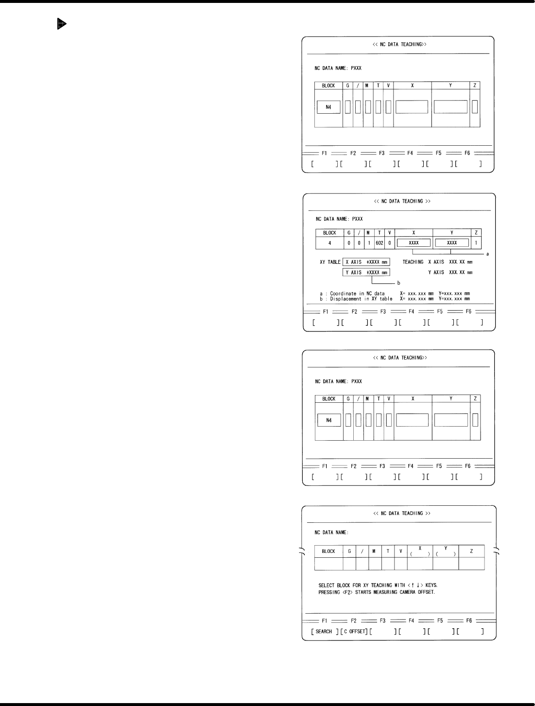
Automatic camera offset
measuring (Y direction)
1. Move the XY table to the insertion position
of N4 block in the NC data.
x Move the cursor to N4 block using np
keys.
x Press ENTER.
x Press F1 (MOVE).
2. Perform XY teaching for X direction
insertion so that the guide pin may be
aligned with the center of the insertion
hole.
3. Write down the coordinate value (a) and
XY table displacement (b) displayed on
the NC DATA TEACHING screen.
4. Alter the NC data.
x Press ENTER.
5. Return to the block select screen.
x Press ESC.
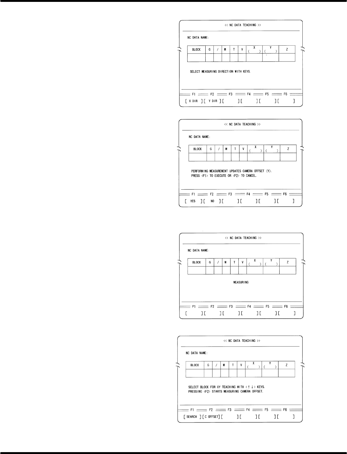
− Measuring in progress −
− Measuring completed −
5.32 Setting Offset Values
SERVICE MANUAL
RH5
5.32−11
DA3SEC−83−9Q0−A0
6. Select Automatic Camera Offset Measuring.
x Press F2 (C OFFSET).
7. Select the measuring direction.
x Press F2 (Y DIR).
8. Execute measuring.
x Press F1.
=REFERENCE=
After measuring is completed, camera
offset (Y) will be automatically overwritten.
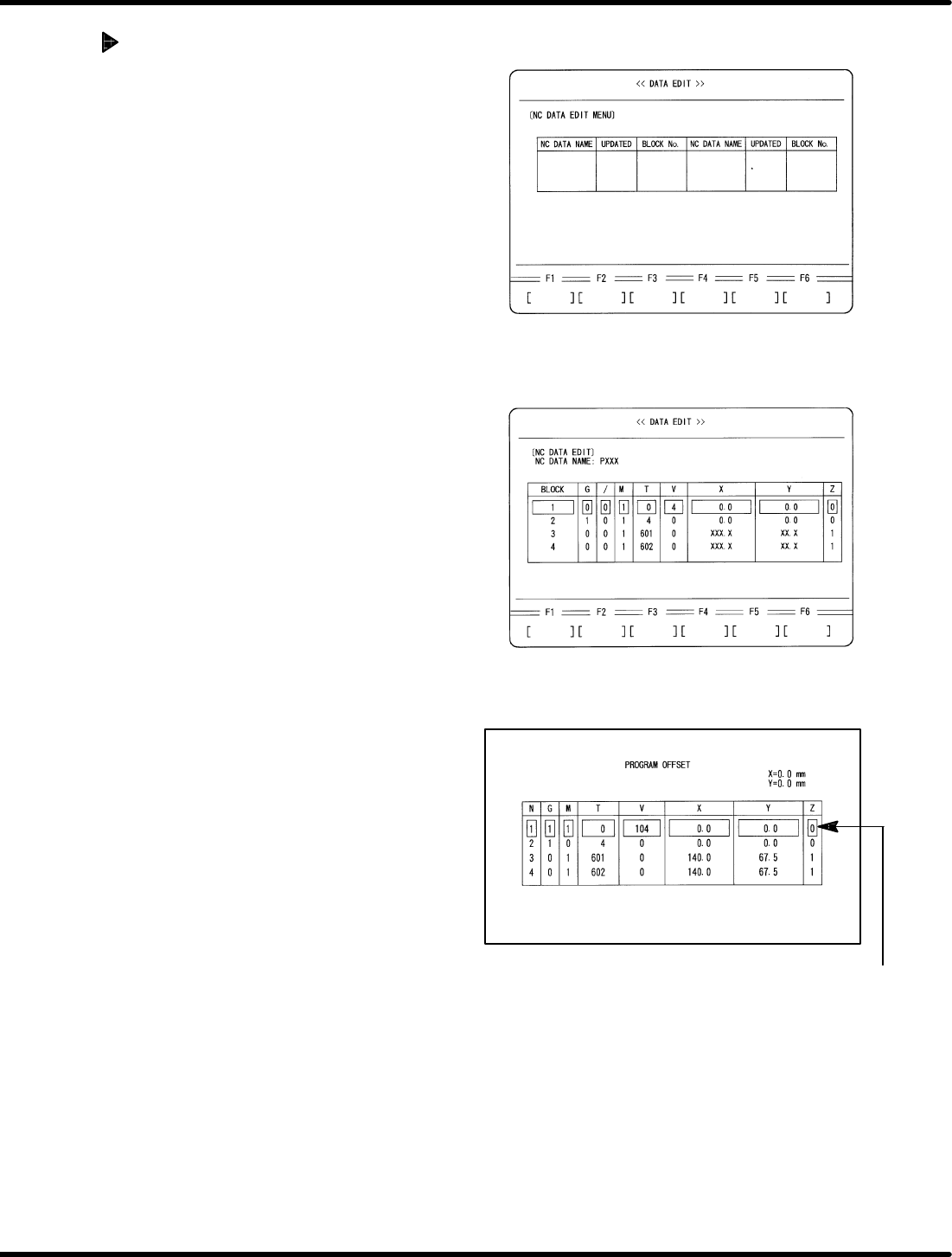
Change V4
to V104
RH5
5.32 Setting Offset Values
SERVICE MANUAL
5.32−12
DA3SEC−83−9Q0−A0
Checking Recognition
Operation
1. Call up the NC data edit screen.
x Press ESC twice.
x Press REQ.
x Press F2 (DATA EDIT).
x Press F1 (NC DATA).
x Press F2 (DATA EDIT).
2. Select an NC data for recognition
adjustment.
x Move the cursor to the name of NC data
for recognition adjustment.
x Press ENTER.
x Press F1 (YES).
3. Change V command of the 1st block in
the selected NC data.
x Change V command in the 1st block
from 4 to 104 as shown left.