Q170226E01.pdf - 第185页
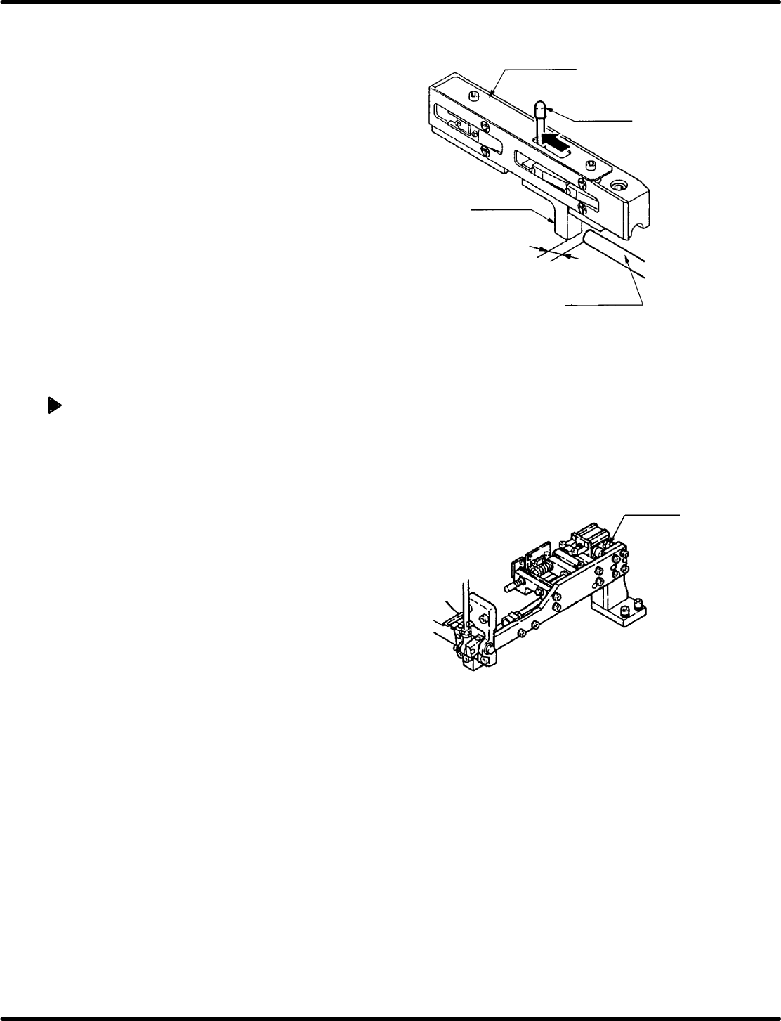
Pusher Spring Shaft Shaft Pusher Gap 0 RH5 5.26 Feeder Unit Feed Pitch and Position Check and Adjustment SERVICE MANUAL 5.26−4 DA3SEC−83−9J0−A0 Replacing/adjusting feed spring 1. Remove the electronic components mounted …
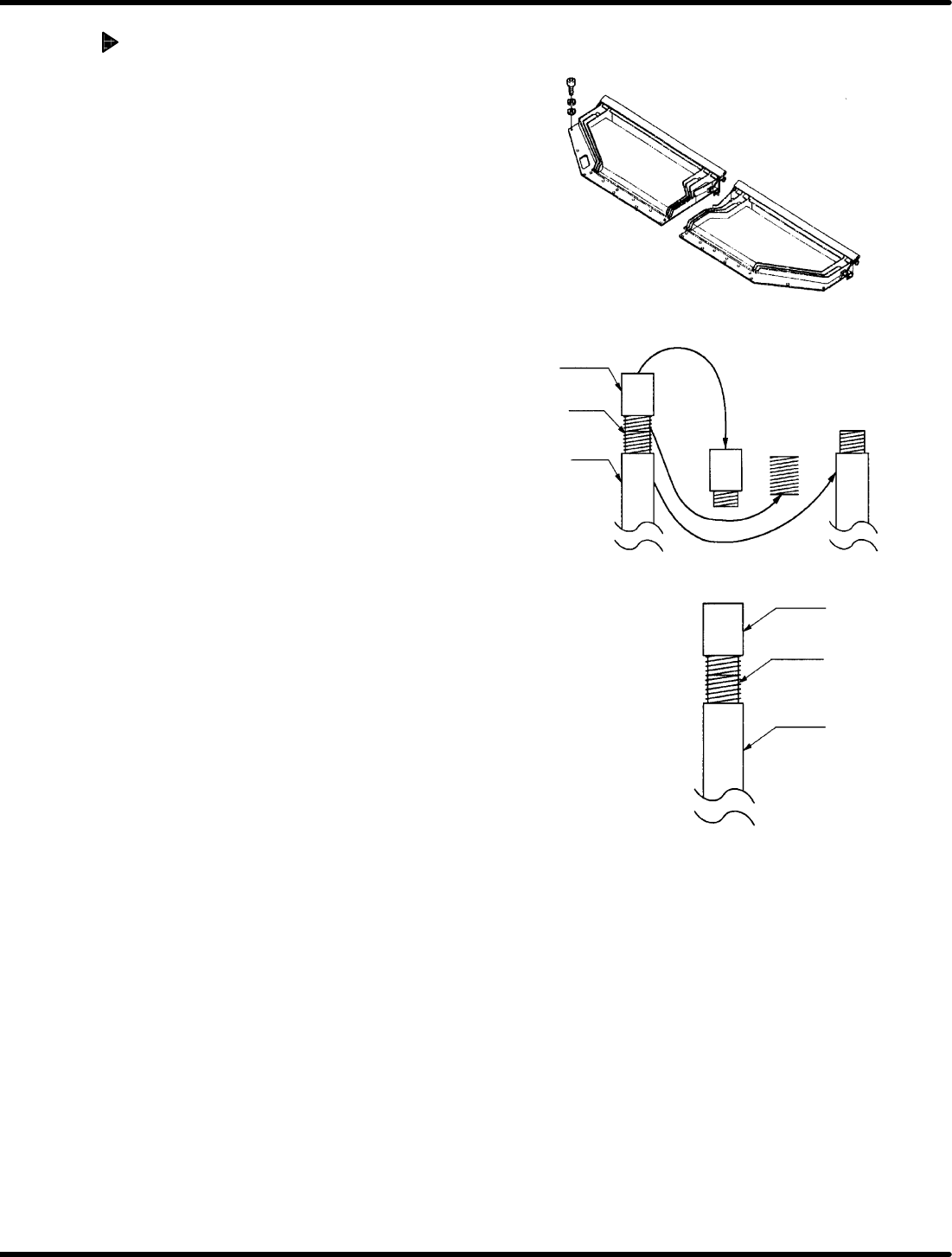
Parts casette
Spring pin
Feed slide
Pusher shaft
Clearance
1.1 mm H 0.1 mm
Cylinder
front/back bolt
5.26 Feeder Unit Feed Pitch and Position Check and Adjustment
SERVICE MANUAL
RH5
5.26−3
DA3SEC−83−9J0−A0
4. Move the spring pin completely in the direction of
arrow and check that the clearance between the
feed slide and pusher shaft is 1.1r0.1 mm using a
thickness gauge when it stops.
=REFERENCE=
The parts cassette has two types; new and old.
Factory−equipped cassettes are the new type.
Clearance of the old type cassettes shall be
0.6r0.1 mm.
5. If the correct clearance cannot be obtained, loosen
the bolts to disengage the pusher shaft.
6. Move the pusher shaft to−and−fro to adjust the
clearance.
7. After adjusting, retighten the bolts and secure the
pusher shaft.
Adjusting feed (Cylinder feed)
1. Turn the hand wheel to set the digital sequence
timer to 0q .
2. Turn OFF the FEED LOCK RELEASE on the
sub−control panel and then turn ON the PARTS
FEEDER.
3. Move the spring pin in the direction of arrow and
check that the clearance between the feed slide
and pusher shaft is 1.1r0.1 mm using a thickness
gauge when it stops.
4. If the correct clearance cannot be obtained, loosen
the front and rear bolts of the cylinder and then
move the cylinder to and fro to adjust the feed
clearance.
5. After adjusting, retighten the bolts and fix the
cylinder.
Pusher
Spring
Shaft
Shaft
Pusher
Gap 0
RH5
5.26 Feeder Unit Feed Pitch and Position Check and Adjustment
SERVICE MANUAL
5.26−4
DA3SEC−83−9J0−A0
Replacing/adjusting feed spring
1. Remove the electronic components mounted
on the Z axis.
2. Cut off the power and air supply and remove
the right top plate of the Z axis.
3. Remove the spring of the feed pusher from
the shaft and then the spring from the end of
the pusher. (Any spring of the two can be
removed first.)
4. Attach a new spring not to have a gap
between the pusher and shaft.
=REFERENCE=
Be sure to attach the spring without any
gap to prevent the clearance to be
changed in feeding the parts cassette.
Added feed limit stopper:
Cam: 0.1
Cylinder:0.1
5.27 Feeder Component Sensor and Component Exhaust Sensor Settings
SERVICE MANUAL
RH5
5.27−1
DA3SEC−83−9K0−A0
5.27 Feeder Component Sensor and Component
Exhaust Sensor Settings
DA3SEC−83−9K0−A0
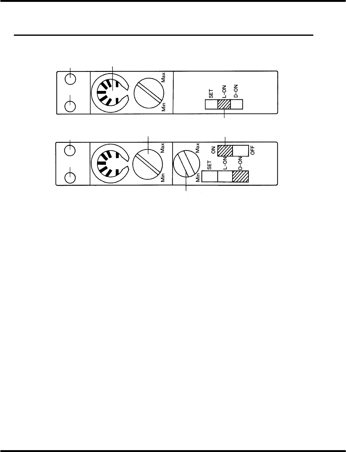
Sentence No.
LED red
LED red
LED green
LED green
Component
exhaust detection
Feed component
detection
Sensitivity indicator
Sensitivity volume
Timer switch
Mode select switch
Timer control volume
5.27.1 Part name
x Red LED: Indicates incoming light is ON.
x Green LED: Indicates stable operation.
x Sensitivity indicator: Allows volume position to be checked.
x Sensitivity control volume: Enables sensitivity adjustment.
x Timer volume: Timer disabled.
x Mode select switch:
SET o Used when adjusting optical axis (Flashing)
L−ON o Light ON
D−ON o Dark ON.
x Timer switch: Timer available. (Switching is disabled.)
5.27.2 Setting methods
x Sensitivity control volume: Turn the dial gradually from Min. until green and red LEDs light up.
x Timer volume: Any position is permissible.
x Mode select switch:
Feed component sensor: Set to D−ON.
Component exhaust sensor: Set to L−ON.
x Timer switch: Either ON or OFF will do.