Q170226E01.pdf - 第364页
8.8 Monitoring I/O Signals SERVICE MANUAL RH5 8.8−3 DA3SEC−85−520−A0 Forced output (Reference) 1. Select “F2” (MONITORING) on the operation screen. 2. Select “F3” (MEMORY) on the monitoring screen. 3. Select “F1” (CPU). …
RH5
8.8 Monitoring I/O Signals
SERVICE MANUAL
8.8−2
DA3SEC−85−520−A0
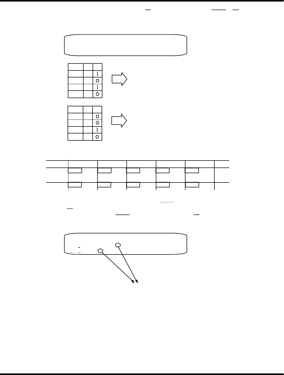
Example 1) If the numbers (2 digits) applied for 07
of the monitoring address 70000 is A2 as shown
below, the following will be revealed according to the input table and I/O status
table.
When 7 Bit is ON, cutter return signal is ON.
When 5 Bit is ON, mechanical lock return signal is ON.
Bit A
7
6
5
4
Bit 2
3
2
1
0
Monitoring screen
ADDRESS CPU 00 01 02 03 04 05 06 07 08 09 0A 0B 0C 0D 0E 0F
70000 ** ** ** ** ** ** ** A2 ** ** ** ** ** ** ** **
When 1 Bit is ON, head swivel lock return signal is ON.
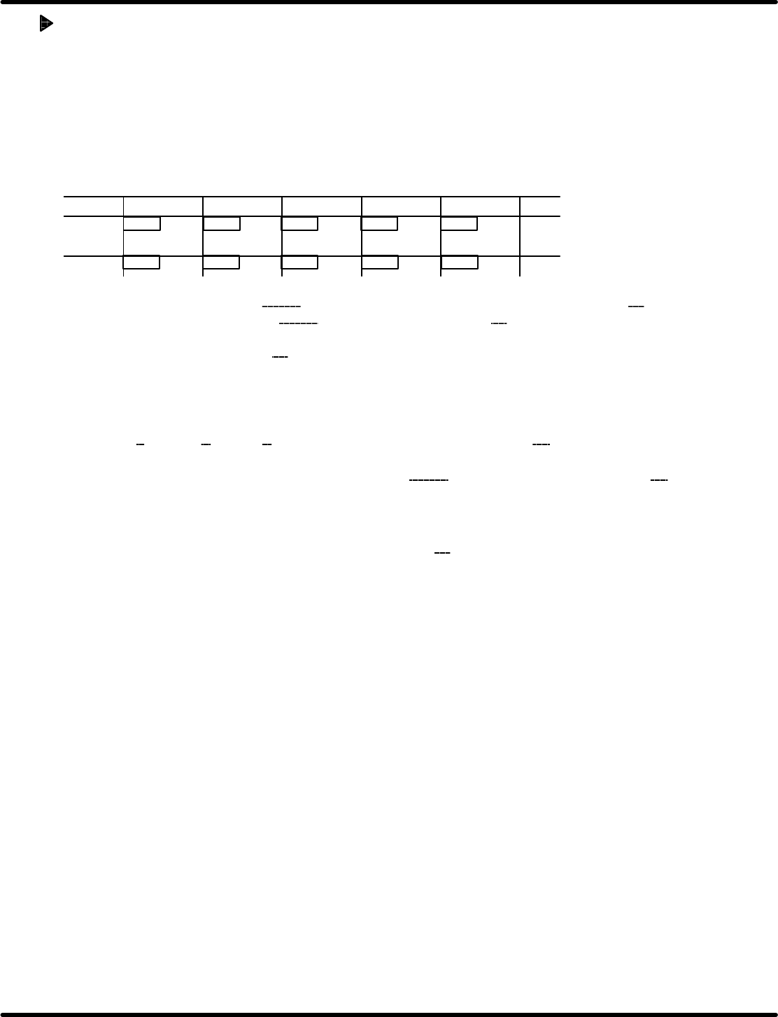
Example 2) To check whether the cut waste drop function is activated:
ADDRESS
7 bit
6 bit 5 bit 4 bit 3 bit
7004 3
37 36 35 34
33
47 46 45 44 43
Transfer chuck
OFF
Transfer chuck
ON
Cut waste drop
Insertion pusher
high pressure
Cutter
Output table − 1
From the output table, select the monitoring address 70040 to check the status of the upper bit (ten’s
digit) under 03
.
Or select the monitoring address 70043
to check the number under 00. (Same results will be
obtained.)
Monitoring screen
ADDRESS CPU 00 01 02 03 04 05 06 07 08 09 0A 0B 0C 0D 0E 0F
70040
** ** ** ** ** ** ** ** ** ** ** ** ** ** ** **
70043 ** ** ** ** ** ** ** ** ** ** ** ** ** ** ** **
In this case, when 5 bit is ON (any of 2*, 3*, 6*, 7*, A*, A*, B*, E*, F* is ON from
comparison table), cut waste drop function is activated.
Similarly, monitoring function enables you to check the status of I/O signals.
8.8 Monitoring I/O Signals
SERVICE MANUAL
RH5
8.8−3
DA3SEC−85−520−A0
Forced output (Reference)
1. Select “F2” (MONITORING) on the operation screen.
2. Select “F3” (MEMORY) on the monitoring screen.
3. Select “F1” (CPU).
4. Call up the output table to perform forced output according to the procedures below.
Example) To turn ON cut waste drop function forcibly:
ADDRESS
7 bit
6 bit 5 bit 4 bit 3 bit
7004 3
37 36 35 34
33
47 46 45 44 43
Transfer chuck
OFF
Transfer chuck
ON
Cut waste drop
Insertion pusher
high pressure
Cutter
Output table − 1
Select the monitoring address 70040 from the output table to check the the number under 03.
Or select the monitoring address 70043
to check the number under 00. (Same results will be
obtained.)
(Here, displayed number is 84
as an example.)
The number within paren ( ) of the BIT in the comparison table to be output is added to the displayed
number.
(As for cut waste drop, it is an upper 5 Bit. So, 2 within paren ( ) of 5 Bit is added to
ten’s digit 8
to make A (8 + 2 =A: hexadecimal). So , the data for output is A4.)
Next, press “F1” (CPU) five times to input the address 70043
. Then input the calculated data (A4)to
“DATA=”.
This forcibly turns ON the cut waste drop function.
To turn OFF the forced output, re−enter the initial number (84
) to “DATA=” in the same manner.
RH5
8.8 Monitoring I/O Signals
SERVICE MANUAL
8.8−4
DA3SEC−85−520−A0
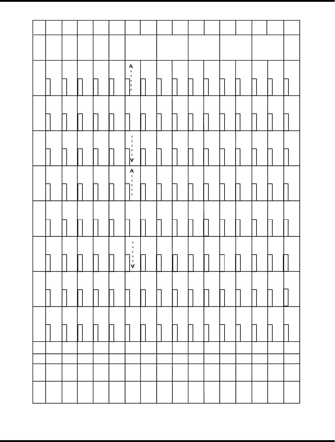
ADDRESS LABEL
BLK DEV
7bit 6bit 5bit 4bit 3bit 2bit
1 bit 0 bit COMMENT
7000 0
7000 1
7000 2
7000 3
7000 4
7000 5
7000 6
7000 7
7000 8
7000 9
7000 A
7000 B
7000 C
7000 D
7000 E
7000 F
00
00
00
00
00
00
00
00
0 100
0 100
0 100
0 100
0 100
0 100
0 100
0 100
02D0
02D2
02D4
02D6
0290
0004
0006
0008
000A
0080
0082
0084
0086
0088
008A
DST
DST
DST
DST
Parallel I/O
0 (SI3−1)
7 (SI3−8) 6 (SI3−7)
CS8
Cut waste drop low
speed
CS16 PH error +
Step start
17 (SI4−2)
27 (SI9−7)
37
47
57
67
77
107
117
127
137
147
157
167
177
Interlock release (R)
(Usually ON)
Unloader pusher
reverse
Vacuum trip
Cutter return
CS24
Transfer chuck condition
32 bit
multidial (0)
16 bit IN
LOOP1
Dial (2)
Dial (0)
16 bit IN
LOOP2
Dial (1)
16 bit IN
LOOP2
Dial (2)
16 bit IN
LOOP2
Handle detection
Insertion
detection 4
CS7
Cutter return
CS15
Intermediate stop
CS23
Feed condition
16 (SI4−1)
26 (SI01−9)
36
46
56
66
76
106
116
126
136
146
156
166
176
Servo lock release
SW
Unloader option PCB
exhaust signal
Insertion
detection 3
Insertion
detection 2
Insertion
detection 1
Cutter forward
1BLOCK stop
Feed return
detection
Unloader pusher
forward
PCB presence
Z axis cover4
(Usually ON)
Interlock release (F)
(Usually ON)
CS6
Cut waste drop high
speed
CS14
Inching stop
5 (SI3−6)
15 (SI3−14)
25 (SI01−8)
35
45
55
65
75
105
115
125
135
145
155
165
175
Z axis cover3
(Usually ON)
Z axis cover2
(Usually ON)
Z axis cover1
(Usually ON)
CS22
Insertion pusher high
pressure
SC safety input
Stocker ready
Mecha lock return
(Feed lock return)
Upper cover rear
(Usually ON)
Transfer cylinder
return check
Feed forward
detection
Unloader rail lower
limit
Walking beam lower
limit
4 (SI3−5)
CS5
14 (SI3−13)
CS13
Extra stop timing
24 (SI01−7)
CS21
Insertion check timing
34
CS29
Handle swivel lock
release
44
SQI0−3
54
64
74
104
114
124
134
144
154
164
174
Mecha lock forward
(Feed lock forward)
Upper cover front
(Usually ON)
Transfer cylinder
forward check (std)
Anvil swivel lock
return
Walking beam
upper limit
Unloader rail upper
limit
3 (SI3−4)
CS4
Intermediate
re−acceleration
13 (SI3−12)
CS12
High speed origin
stop
23 (SI01−6)
CS20
Anvil lock release
33
CS28
Transfer chuck (MANU
cam interlock)
43
SQI0−2
53
Bush arm
forward limit
63
73
103
113
123
133
143
153
163
173
Parts exhaust
pre−detection
Invert swivel
reverse limit
Loader rail
lower limit
Anvil swivel lock
forward
Unloader exit PCB
detection
Special 1 block
stop (Normally ON)
Z axis − safety limit
(Normally OFF)
Z axis + safety limit
(Normally OFF)
162
Front cover
(Usually ON)
2 (SI3−3)
CS3
Z axis hold condition
12 (SI3−11)
CS11
Intermediate
speed origin stop
22 (SI6−6)
CS19
Anvil Y direction lock
32
CS27
Guide chuck (MANU
cam interlock)
42
P791
Fan motor alarm
52
PC board
supply ready
62
72
102
112
122
132
142
152
Feed component
detection
Invert swivel
forward limit
Loader rail
upper limit
Unloader entrance
PCB detection
safety input (Z axis
intermediate sensor)
172 171
161
Y axis safety limit
(Normally OFF)
Unloader cover
(Usually ON)
151
Pressure SW
(Usually ON)
141
Clamp detection
131
111
121
Loader exit PCB
detection
51
L side connection
61
71
101
Head swivel lock
return
Invert unit
lower limit
1 (SI3−2)
CS2
Z hold
11 (SI3−10)
CS10
Low speed origin
stop
21 (SI6−5)
CS18
Head lock release
31
CS26
Insertion chuck (MANU
cam interlock)
41
Image scan
complete
10 (SI3−9)
CS9
Origin
20 (SI6−4)
CS25
Operation monitor
data shift timing
50
PC board supply
forward limit
60
30
Head swivel lock
forward
40
Emergency stop
signal
CS17
Head Y direction lock
70
110
120
Loader entrance
PCB detection
100
Invert unit
upper limit
140
150
Cover presence
(OFF: Cover Yes)
130
DST trip
Loader cover
(Usually ON)
Thermal ON
170
160
X axis safety limit
(Normally OFF)
Input Table−1 (Actual Machine) RH5
CS1
XY hold
UL side connection
Signal PC board
supply reverse limit
Signal bush arm
reverse limit