Q170226E01.pdf - 第187页
RH5 5.27 Feeder Component Sensor and Component Exhaust Sensor Settings SERVICE MANUAL 5.27−2 DA3SEC−83−9K0−A0 = MEMO =
5.27 Feeder Component Sensor and Component Exhaust Sensor Settings
SERVICE MANUAL
RH5
5.27−1
DA3SEC−83−9K0−A0
5.27 Feeder Component Sensor and Component
Exhaust Sensor Settings
DA3SEC−83−9K0−A0
Sentence No.
LED red
LED red
LED green
LED green
Component
exhaust detection
Feed component
detection
Sensitivity indicator
Sensitivity volume
Timer switch
Mode select switch
Timer control volume
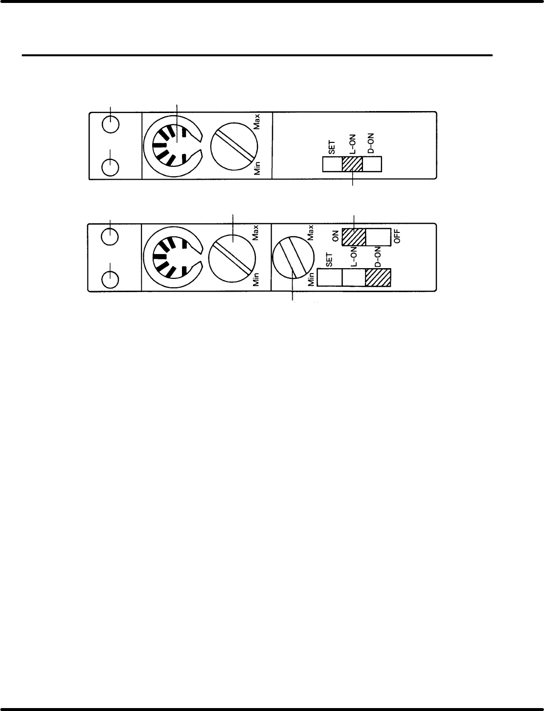
5.27.1 Part name
x Red LED: Indicates incoming light is ON.
x Green LED: Indicates stable operation.
x Sensitivity indicator: Allows volume position to be checked.
x Sensitivity control volume: Enables sensitivity adjustment.
x Timer volume: Timer disabled.
x Mode select switch:
SET o Used when adjusting optical axis (Flashing)
L−ON o Light ON
D−ON o Dark ON.
x Timer switch: Timer available. (Switching is disabled.)
5.27.2 Setting methods
x Sensitivity control volume: Turn the dial gradually from Min. until green and red LEDs light up.
x Timer volume: Any position is permissible.
x Mode select switch:
Feed component sensor: Set to D−ON.
Component exhaust sensor: Set to L−ON.
x Timer switch: Either ON or OFF will do.

RH5
5.27 Feeder Component Sensor and Component Exhaust Sensor Settings
SERVICE MANUAL
5.27−2
DA3SEC−83−9K0−A0
= MEMO =
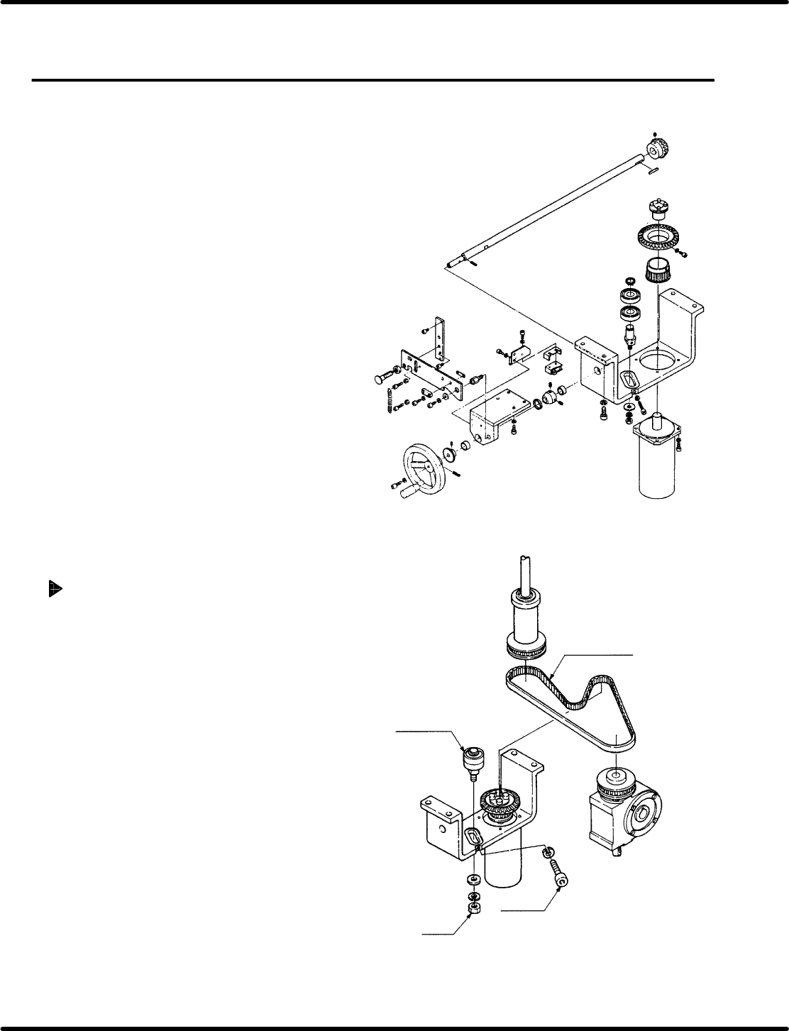
Timing belt
Bearing
Bolt A
Nut A
5.28 Main Drive Unit Timing Belt Replacement and Adjustment
SERVICE MANUAL
RH5
5.28−1
DA3SEC−83−9L0−A0
5.28 Main Drive Unit Timing Belt Replacement and
Adjustment
DA3SEC−83−9L0−A0
Sentence No.
When to perform
x When the timing belt slips due to wear
or damage.
Required tools
x Allen wrench
Timing belt replacement
1. Loosen the bolt A and the nut A.
2. Move the bearing to detach the timing belt.
3. Put on a new timing belt.
4. Fit the bearing with the timing belt and
ensure tension with the bolt A.
5. Retighten the nut A.