Q170226E01.pdf - 第148页
5.15 Lead Cutter and T ape Cutter Replacement and Adjustment SERVICE MANUAL RH5 5.15−3 DA3SEC−83−8XO−A0 T ape cutter and lead cutter mounting and check 1. Fix the tape cutters (A) and (B) with bolts A1 and B1and lead cut…
RH5
5.15 Lead Cutter and Tape Cutter Replacement and Adjustment
SERVICE MANUAL
5.15−2
DA3SEC−83−8XO−A0
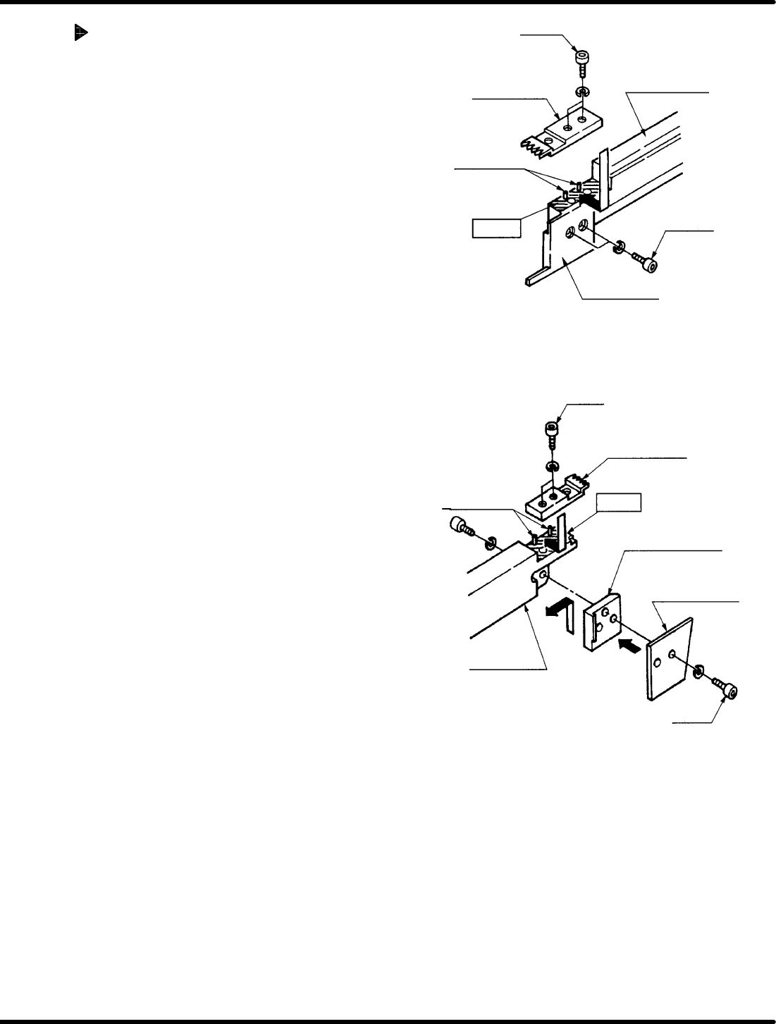
Temporarily securng tape cutter and
lead cutter temporarily
1. Clean the mounting surface of the lead cutter
(B) and tape cutter (B).
2. Press the lead cutter (B) such that it is flush
against the mounting surface of the positioning
pins.
3. Check that there is no gap gauge larger than
0.01 mm can be seen between the positioning
pins and lead cutter (B). Then, temporarily
secure surface of it in place with bolt B1 (x 2)
4. Press the tape cutter (B) against the contact
surface at the end of the cutter body (B) and
raise it fully to secure with bolt B2 (x 2)
temporarily.
5. As for the lead cutter (A), follow the same
procedure with the lead cutter (B) and lock it in
place temporarily and check the fit with a gap
gauge.
6. Secure the tape cutter (A) temporarily in the
same manner.
=CHECK=
x Take note of the length of the lead cutter fitting
bolt. (M3 x 6)
(Using a longer bolt ma cause the interference
with the cut waste pusher .)
=CHECK=
When the lead cutter and tape cutter being
installed, be sure to attach the lead cutter first.
Bolt B1
Lead cutter (B)
Positioning pin
Cutter body (B)
Bolt B2
Tape cutter (B)
Mounting
surface
Mounting
surface
Bolt A1
Lead cutter (A)
Positioning pin
Cutter body block
Tape cutter (A)
Cutter body (A)
Bolt A2
5.15 Lead Cutter and Tape Cutter Replacement and Adjustment
SERVICE MANUAL
RH5
5.15−3
DA3SEC−83−8XO−A0
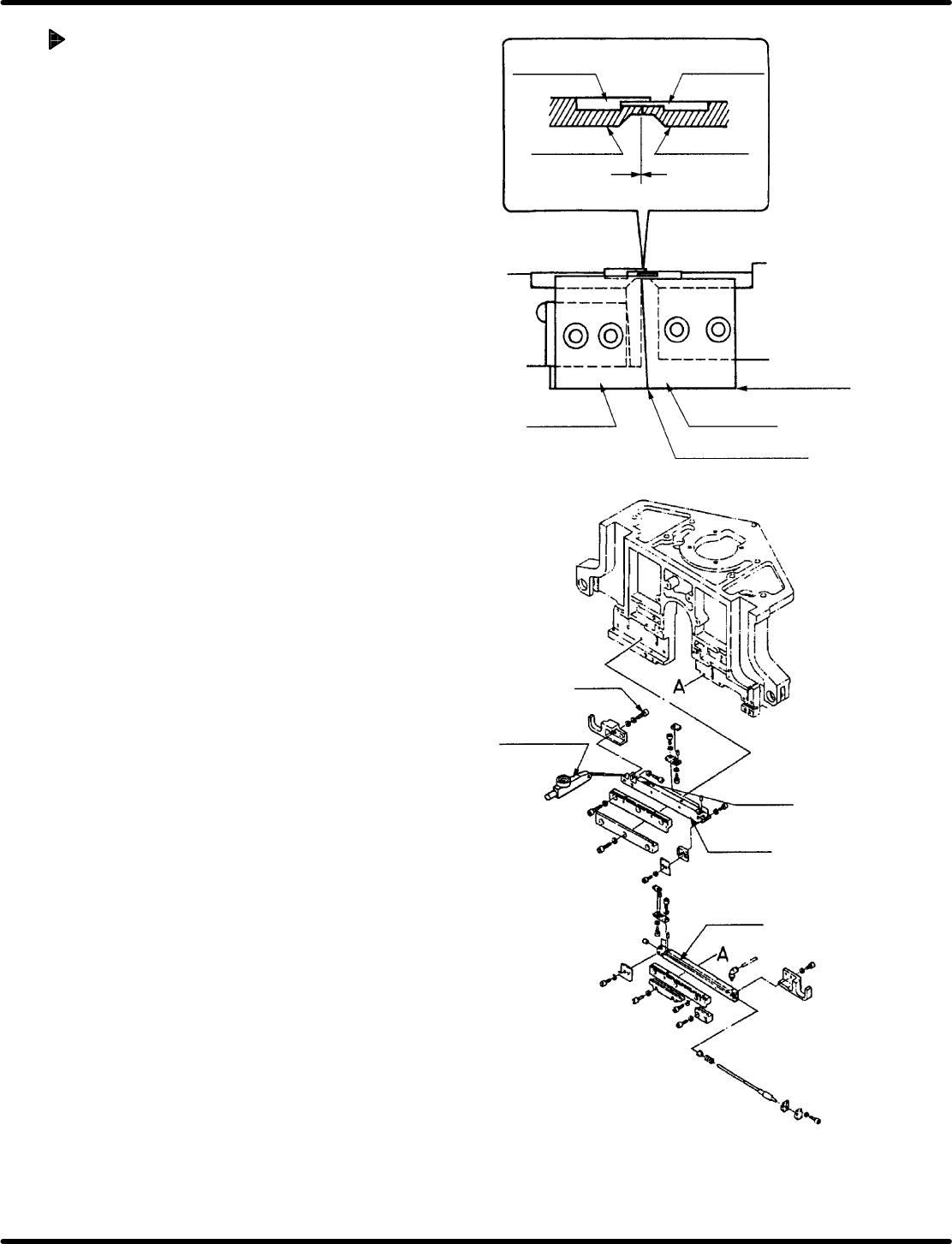
Tape cutter and lead cutter
mounting and check
1. Fix the tape cutters (A) and (B) with bolts A1
and B1and lead cutters (A) and (B) with A2
and B2 respectively.
2. Check the bottom edges of the tape cutter (A)
and tape cutter (B) are level with one another.
3. Release the fitting bolt (x 2) of the cutter 2
slider.
4. Turn the hand wheel to set the digital
sequence timer to 315q.
5. Move the cutter 2 slider to the blade surfaces
of the lead cutters (A) and (B) which engaged
without leaving gap and secure them with the
fitting bolt (x 2).
6. Turn the hand wheel to set the digital
sequence timer to 0q.
7. Set the dial gauge on the cutter 2 slider.
8. Release the fitting bolt (x 2) of the cutter 2
slider again and retighten 2 bolts with the
drive amount 0.1 to 0.15 mm.
Lead guide A
Lead guide B
Lead cutter A
Lead cutter B
Tape cutter A
Tape cutter B
Cutter overlap here
Make sure bottom
edges are level
Bolt
Level−operated
dial gauge
Cutter 2
Slider
Cutter 1

RH5
5.15 Lead Cutter and Tape Cutter Replacement and Adjustment
SERVICE MANUAL
5.15−4
DA3SEC−83−8XO−A0
= MEMO =