Q170226E01.pdf - 第221页
RH5 5.35 M e c hanical V alve Replacement and Adjustment SERVICE MANUAL 5.35−4 DA3SEC−83−9T0−A0 = MEMO =

5.35 Mechanical V alve Replacement and Adjustment
SERVICE MANUAL
RH5
5.35−3
DA3SEC−83−9T0−A0
4. In SEMI mode, turn the hand wheel to
check the opening/closing timing of the
respective chuck.
=REFERENCE=
Transfer chuck:
Open: 86q , Close: 265q
Insertion chuck:
Open: 200q , Close: 81q
Guide chuck:
Open: 214q
The tolerance of open/close timing
shall be r 1q.
=REMARKS=
Refer to ‘5.12 Insertion Head Chuck
Opening/Closing Timing
Check/
Adjustment’.

RH5
5.35 Mechanical V alve Replacement and Adjustment
SERVICE MANUAL
5.35−4
DA3SEC−83−9T0−A0
= MEMO =
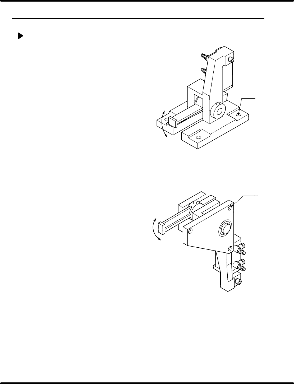
(4−M8)
(3−M8)
(Insertion head swivel lock cylinder)
(Anvil swivel lock cylinder)
5.36 Y Lock Cylinder Replacement and Adjustment
SERVICE MANUAL
RH5
5.36−1
DA3SEC−83−9U0−A0
5.36 Y Lock Cylinder Replacement and Adjustment
DA3SEC−83−9U0−A0
Sentence No.
Replacing/adjusting Y lock cylinder
1. Turn the hand wheel to set the digital
sequence timer to 100q.
2. Cut off the power to the machine and air
supply.
3. Remove the bolt attaching Y lock cylinder.
(Insertion head: 4−M8, Anvil: 3−M8)
4. Disconnect air piping and remove the lead
switch.
=CHECK=
Mark the air piping and lead switch
before removing.
5. Detach the old cylinder.
=REFERENCE=
The cylinder can be detached by removing
the bolt (2−M4) and disengaging the rod
end nut.
6. Assemble a new cylinder and apply grease
to the fulcrum pin, etc.
=CHECK=
Be careful not to tighten the bolt (2−M4)
extremely. Too tightened bolt may
impair the movement of the cylinder.
(The cylinder must move smoothly by
hand.)
7. Install the lead switch and air piping in the
original state.
=CHECK=
Surely install the lead switch and air
piping in its original position.
8. Lock the fitting bolt of the Y lock cylinder
temporarily.
(Insertion head: 4−M8, Anvil: 3−M8)
9. Supply air and turn ON power to the
machine.