Q170226E01.pdf - 第165页
RH5 5.19 Anvil Parallelism Check and Adjustment SERVICE MANUAL 5.19−4 DA3SEC−83−9BO−A0 Adjusting parallelism (2) (Adjusting X stopper) 1. Set the digital sequence timer to 210 q . 2. Fit the anvil rotation stopper (X) to…
5.19 Anvil Parallelism Check and Adjustment
SERVICE MANUAL
RH5
5.19−3
DA3SEC−83−9BO−A0
Adjusting parallelism (1)
1. Check the swing accuracy at 210q in both X
and Y directions on the digital sequence
timer.
2. If both swing accuracies are not at right
angle (90q), disengage the bolt D (x 2) and
adjust the accuracies using the adjusting
screw. (It is not necessary to measure the
exact value. Set to right angle visually.)
Example:
x If the swing exceeds by 0.6 mm in X
direction, adjust the swing not to
exceed by 0.6 mm in Y direction to set
a high angle.
x If the swing is below 1.5 mm in X
direction, adjust the swing to exceed by
1.5 mm in Y direction to set a right
angle.
3. Secure the bolt D (x 2).
4. Loosen the bolt C (x 3) of the stage (4) and
adjust the 210q swing (X direction) to be 0.
(Adjust the swing to be within 0.04 mm while
lightly tapping the stage (4) with the copper
rod.)
5. Retighten the bolt C (x 3) of the stage (4).
6. Use the hand wheel,to set the digital
sequence timer to 210q (Y direction).
(Make sure the accuracy in Y direction is
within 0.04 mm.)
=REFERENCE=
If the accuracy is not obtained within the
given range, repeat steps 1 through 6.
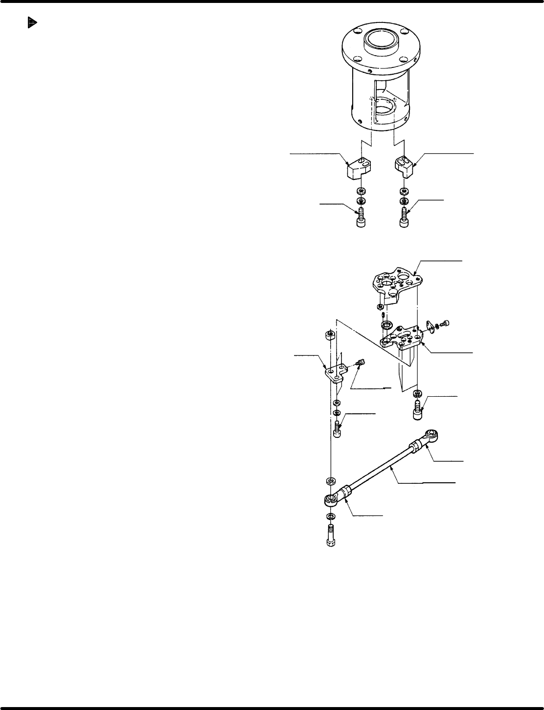
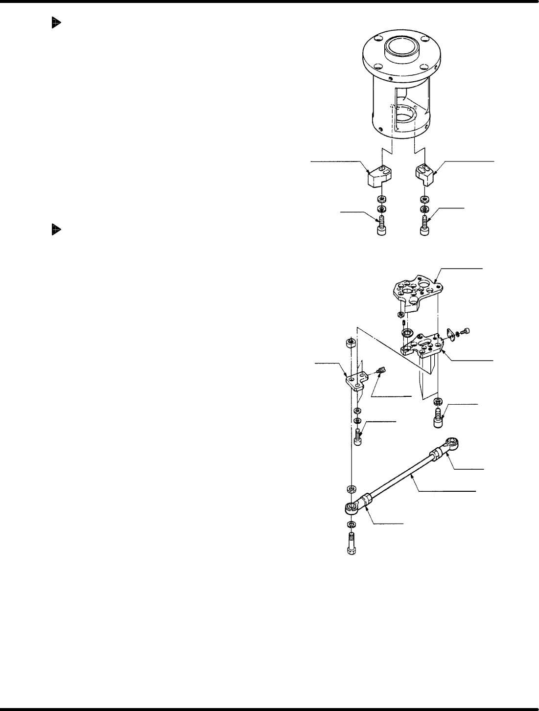
Anvil rotation
stopper (X)
Anvil rotation
stopper (Y)
Bolt B
Bolt A
Stage (3)
Stage (4)
Slider
Adjusting
screw
Bolt C
Nut B
Bolt D
Connecting rod
Nut A
RH5
5.19 Anvil Parallelism Check and Adjustment
SERVICE MANUAL
5.19−4
DA3SEC−83−9BO−A0
Adjusting parallelism (2) (Adjusting
X stopper)
1. Set the digital sequence timer to 210q.
2. Fit the anvil rotation stopper (X) to the
rotating panel and secure it with bolt A (x 2).
3. Measure the accuracy again.
=REFERENCE=
If the above−mentioned parallelism
cannot be obtained, repeat the steps 1
through 3.
Adjusting parallelism (3) (Adjusting
Y stopper)
1. T urn ON Y INSERT on the sub−control panel
and set the digital sequence timer to 210q.
2. Fit the anvil rotation stopper (Y) to the
rotating panel and secure it with bolt B (x 2).
3. Measure the accuracy again.
=REFERENCE=
If the above−mentioned parallelism
cannot be obtained, repeat the steps 1
through 3.
Anvil rotation
stopper (X)
Anvil rotation
stopper (Y)
Bolt B
Bolt A
Stage (3)
Stage (4)
Slider
Adjusting
screw
Bolt C
Nut B
Bolt D
Connecting rod
Nut A
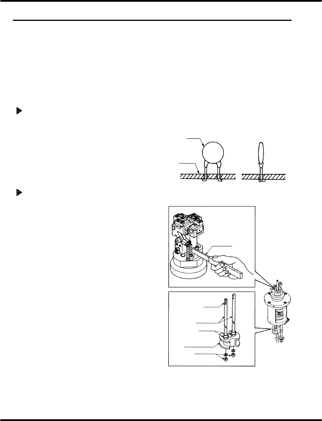
Parts
PCB
Gap gauge
(Over 0.5 mm)
Pusher
Pusher rod
Top nut
(M8)
Cam follower
holder (B)
Bottom nut
(M6)
5.20 Anvil Lower Clinch Stroke Check and Adjustment
SERVICE MANUAL
RH5
5.20−1
DA3SEC−83−9C0−A0
5.20 Anvil Lower Clinch Stroke Check and Adjustment
DA3SEC−83−9C0−A0
Sentence No.
When to perform
x When leads of inserted parts are overly
or insufficiently clinched.
Required tools
x Allen wrench
x Slotted screwdriver
Clinching check
1. Set the machine to the auto mode and
insert some parts checking clinching is
performed properly.
Adjusting clinch stroke
1. Set the machine to the auto mode and turn
the hand wheel until the anvil is in the cut
and clinch state.
2. Loosen the bottom nut (x 2) of anvil lower
cam follower holder (B). Insert a gap gauge
no smaller than 0.5 mm between the anvil
chuck body and pusher.
=REFERENCE=
In adjusting stroke, leave the gap
gauge in place to prevent the anvil’s
pusher from turning.