Q170226E01.pdf - 第133页
RH5 5.1 1 Insertion Head Center Position Check and Adjustment SERVICE MANUAL 5.1 1−2 DA3SEC−83−8T O−A0 Insertion chuck centering 1. Loosen the bolt fixing insertion chuck in place. Lift the insertion chuck body upwards b…
5.11 Insertion Head Center Position Check and Adjustment
SERVICE MANUAL
RH5
5.11−1
DA3SEC−83−8TO−A0
5.11 Insertion Head Center Position Check and
Adjustment
DA3SEC−83−8TO−A0
Sentence No.
When to perform
x When inserted parts are often slanted.
x When insertion errors occur frequently.
Required tools
x Allen wrench
x T−wrench
x Lever−operated dial gauge
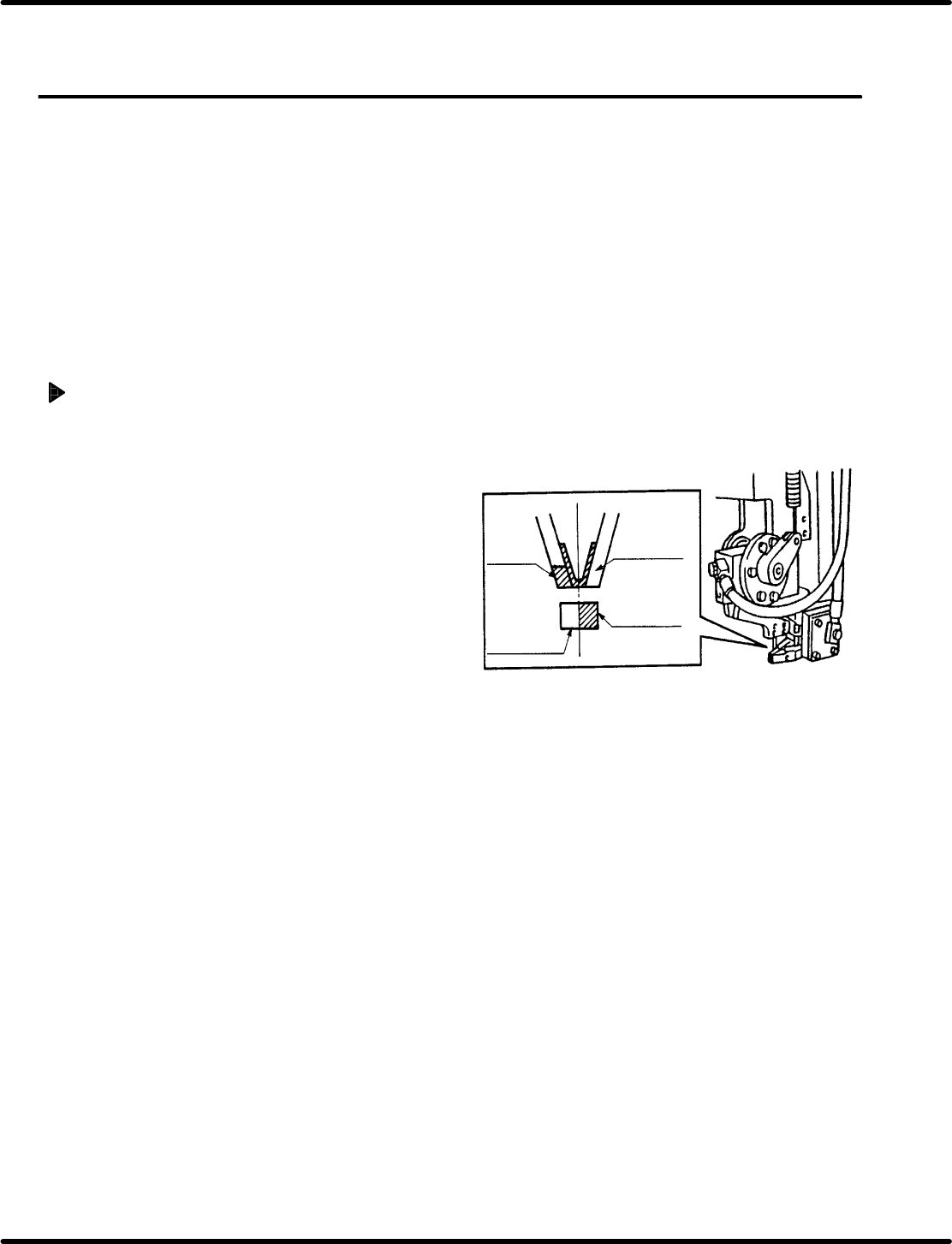
Guide chuck and insertion chuck
centering check
1. Turn the hand wheel until the cam shaft is
approximately at the 210q position on the
digital sequence timer.
=REFERENCE=
Use the guide chuck as a reference when
centering the insertion chuck, transfer
chuck, cutter and parts feeder .
2. Paint the side surface of the insertion chuck
and guide chuck white. Then visually check
the centering.
=CHECK=
Paint only one side of each chuck.
Insertion
chuck
Paint this
part white
Paint this
part white
Guide chuck
RH5
5.11 Insertion Head Center Position Check and Adjustment
SERVICE MANUAL
5.11−2
DA3SEC−83−8TO−A0
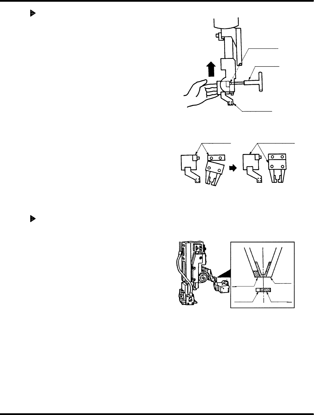
Insertion chuck centering
1. Loosen the bolt fixing insertion chuck in
place. Lift the insertion chuck body upwards
by hand. While keeping it flush against the
head fulcrum shaft, move it left and right until
centered.
=CHECK=
Keep the insertion chuck flush against the
head fulcrum shaft when adjusting.
Insertion chuck and transfer chuck
centering check
1. Turn the hand wheel until the cam shaft is
approximately at the 100q position on the
digital sequence timer.
2. Paint the tip of the transfer chuck and the
side surface of the insertion chuck white.
Press INSERT CHUCK CLOSE on the
sub−control panel and visually check parts
are centered.
=REFERENCE=
x Paint only one side of each chuck.
x The center check can be also done by
detecting no moving by closing the insert
chuck after inserting the thickness gauge
(0.3−0.5mm) into the transfer chuck.
Paint this
part whiter
Paint this
part whiter
Insertion
chuck
Transfer
chuck
Bolt fixing
insertion chuck
T−wrench
Head fulcrum
Insertion chuck
body
(NG) (OK)
5.11 Insertion Head Center Position Check and Adjustment
SERVICE MANUAL
RH5
5.11−3
DA3SEC−83−8TO−A0
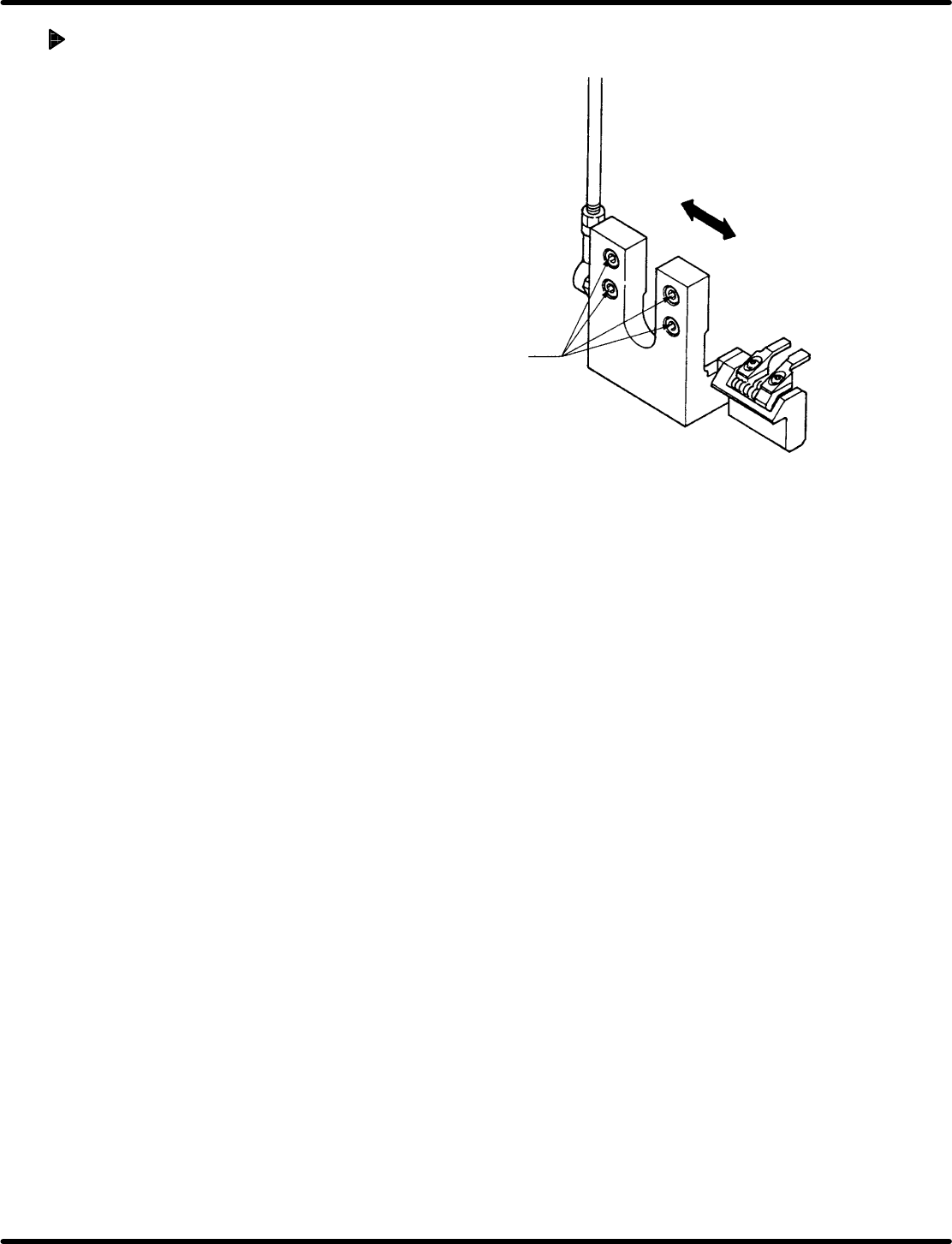
Transfer chuck centering
1. Loosen the bolts (x 4) fixing the bearing in
place.
Then move the bearing left and right until
centered.
2. After adjusting, check centering again.
3. Check the transfer chuck and cutter are
centered and adjust when necessary.
4. Check the positions of the transfer chuck
and the parts feeder. When necessary,
adjust the origin position of the parts feeder.
Bolt
Bearing