Q170226E01.pdf - 第301页
RH5 8.3 List of Jumper Switch Settings SERVICE MANUAL 8.3−4 DA3SEC−85−540−B0 Bus interrupt I/O setting − JP9, 10 * INTL * MBINT * ERROR * INT2IN * INTH * INT6 * INT7 * INT5 * INT4 * INT3 * INT2 * INT1 * INT0 CNC board ad…
8.3 List of Jumper Switch Settings
SERVICE MANUAL
RH5
8.3−3
DA3SEC−85−540−B0
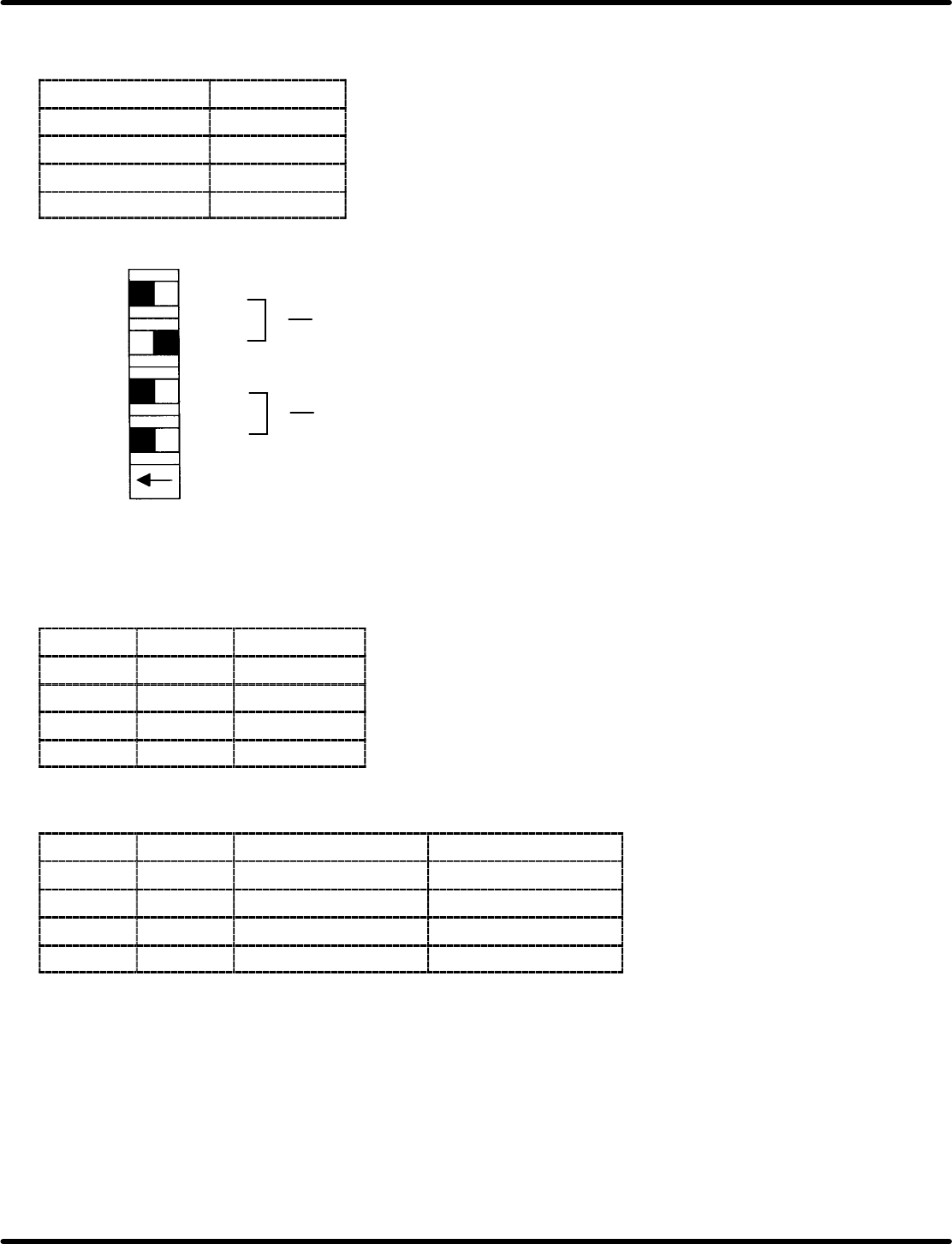
Output pulse CW/CCW function and multiplication changeover switch −
DSW4 to 7
DIP switch Axis
DSW4 1st axis
DSW5 2nd axis
DSW6 3rd axis
DSW7 4th axis
Multiplication
changeover
CW/CCW function
changeover
S0
S1
S2
S3
1
2
3
4
ON OFF
DSW
(1) Multiplication changeover
S2
S3 Multiplication
ON ON x1
ON OFF x2
OFF ON x4
OFF OFF Inhibited
(2) CW/CCW changeover
S0
S1 CW signal CCW signal
ON ON CW positive logic CCW positive logic
OFF ON POUT positive logic PDIR positive logic
ON OFF CW negative logic CCW negative logic
OFF OFF POUT negative logic PDIR negative logic
RH5
8.3 List of Jumper Switch Settings
SERVICE MANUAL
8.3−4
DA3SEC−85−540−B0
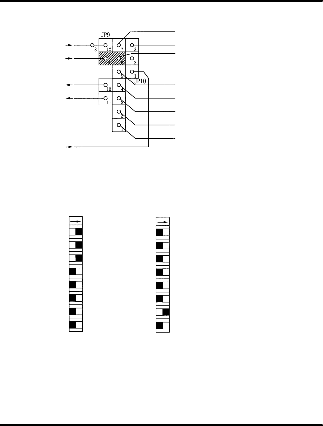
Bus interrupt I/O setting − JP9, 10
* INTL
* MBINT
* ERROR
* INT2IN
* INTH
* INT6
* INT7
* INT5
* INT4
* INT3
* INT2
* INT1
* INT0
CNC board address setting switch − DSW2, 3
Permits base address setting on P2 bus of this board.
* AD10
* AD11
* AD12
* AD13
* ADR20
* ADR21
* ADR22
* ADR23
DSW2 DSW3
ON ON
Address in the above setting is for
74000H.
8
7
6
5
4
3
2
1
8
7
6
5
4 * ADRC
3 * ADRD
2 * ADRE
1 * ADRF
8.3 List of Jumper Switch Settings
SERVICE MANUAL
RH5
8.3−5
DA3SEC−85−540−B0
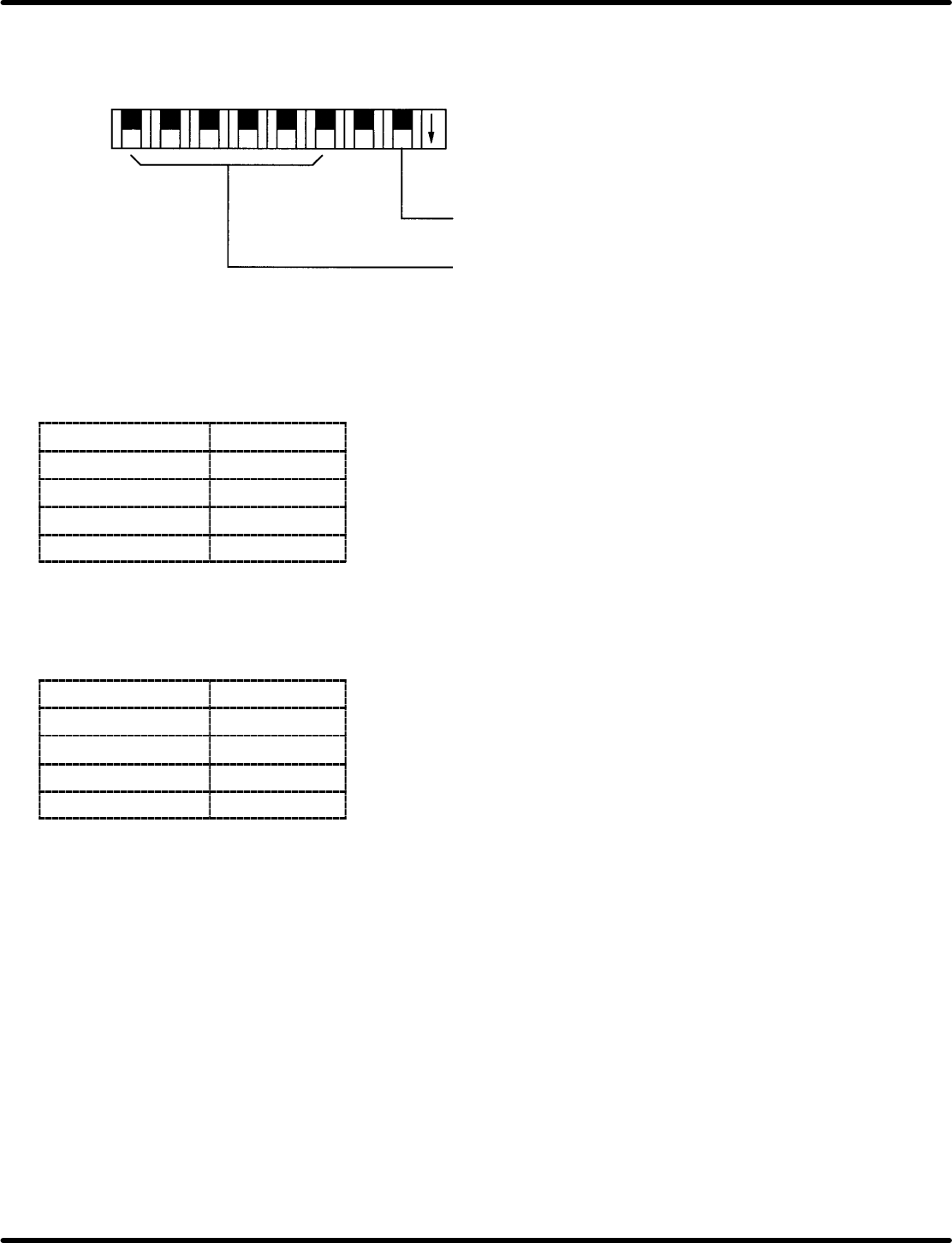
General−purpose input switch on the main side − JP9, 10
Permits leading from main PIO. ON: 0, OFF: 1
Not used
General−purpose
switch
1 23 45678
ON
Offset adjusting volume − VRB1 to 4
Enables adjustment of command output voltage offset.
Volume
Axis
VRB1 1st axis
VRB2 2nd axis
VRB3 3rd axis
VRB4 4th axis
Gain fine−adjusting volume − VRA1 to 4
Gain can be fine−adjusted around the setting voltage 1 (command output voltage).
Gain
Axis
VRA1 1st axis
VRA2 2nd axis
VRA3 3rd axis
VRA4 4th axis