Q170226E01.pdf - 第375页
RH5 8.8 Monitoring I/O Signals SERVICE MANUAL 8.8−14 DA3SEC−85−520−A0 ADDRESS LABEL BLK DEV 7b i t 6b i t 5b i t 4b i t 3b i t 2b i t 1 bit 0 bit COMMENT 7014 0 7014 1 7014 2 7014 3 7014 4 7014 5 7014 6 7014 7 7014 8 701…
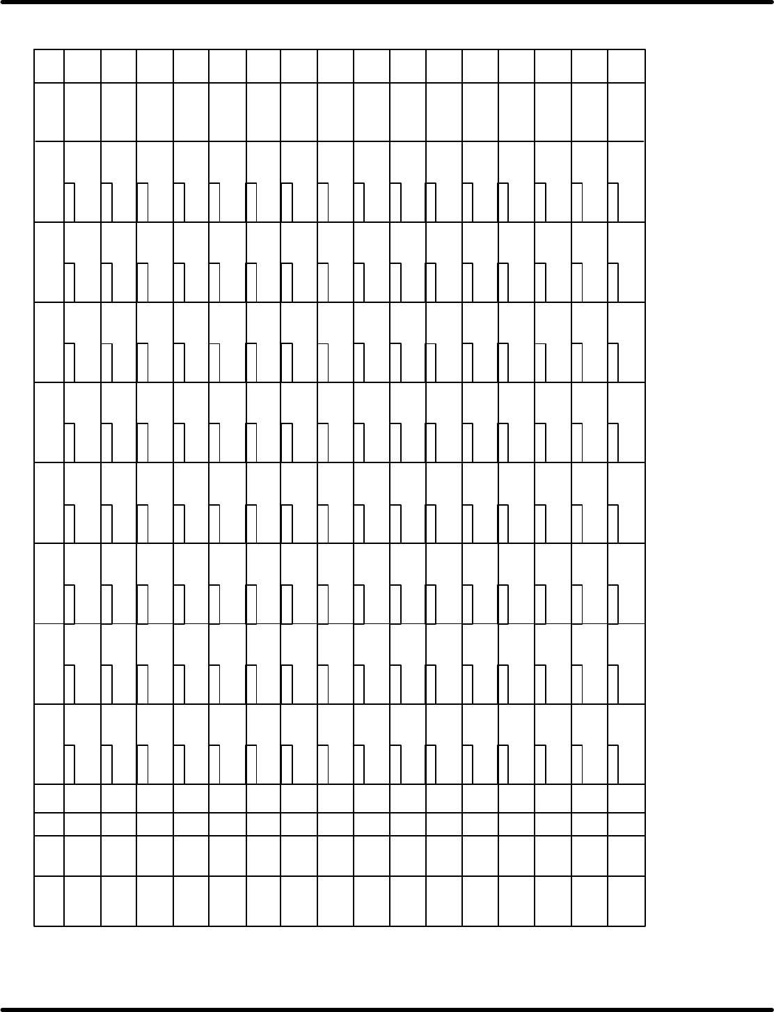
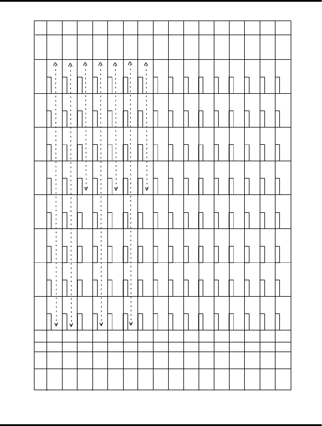
8.8 Monitoring I/O Signals
SERVICE MANUAL
RH5
8.8−13
DA3SEC−85−520−A0
ADDRESS LABEL
BLK DEV
7bit 6bit 5bit 4bit 3bit 2bit
1 bit 0 bit COMMENT
7013 0
7013 1
7013 2
7013 3
7013 4
7013 5
7013 6
7013 7
7013 8
7013 9
7013 A
7013 B
7013 C
7013 D
7013 E
7013 F
Error total
207
217 *
227
237
247
257
267 **2
277
307
317 W. adjust
327
337
347
367 W . adjust
377
216 *
226
236
246
256
266
276
306
316
326
336
346
356
366
376
205
215 *
225
235
245
255
265
275
305
315
325
335
345
355
365
375
206
200
371
361
351
341
331
31 1 *1
321
251
261
271
301
201
211
221
231
241 .*
210 *
220 *
250
260
230
240 *
270
310
320
300
340
350
330
370
360
203
213 *
223
233 Alpine
243
253
263
273
303
313 *1
323
333
343
353
363
373
362
202
212 *
222
232
242
252
262
272
302
312
322
332
342
352
372
204
214 *
224
234
244
254
264
274
304
314 *1
324
334
344
354
364
374
Link Table−4 RH5
5 200
5 200
5 200
5 200
5 200
5 200
5 200
5 200
5 300
5 300
5 300
5 300
5 300
5 300
5 300
5 300
Rail down error
PCB SET error
X axis operation
time over
Transfer cylinder
forward error
Arm down error
Error total 1
Clamp error
Loading ready
error
Reference pin
motor is not OFF.
Servo lock is not
engaged.
Loader belt
motor is turning.
Improper anvil
direction
W. adjust XY
motor is not OFF
Feed operation
error
Backup reverse
error
Transfer cylinder
reverse error
Guide pin recognition
lock error
Servo lock is
not engaged.
Feeder operating
XY interlock is
ON.
Servo release
error
Rail up error
Cam shaft
rotation error
All distortion
OFF
Insertion error
Loader rail is not
at upper limit.
Edge positioning
ON error
Forward limit
signal is sent.
Transfer cylinder
has not returned.
Error occurred
Head anvil swivel
lock error
XY axis is not at
origin.
Clamp detection
is not ON.
Forward limit
signal is sent.
Out of machine
origin
Invert unit is not
at upper limit.
Transfer
system
error
Handle is
engaged.
Start ready
Head rotation,
insert start
condition error
Improper cam
shaft angle
XY table is not
at origin.
Invert chuck is
not open.
Invert error
Arm up error
Error total 2
Reference pin
motor is not ON.
Transfer
system
error
Parts exhaust
**1
XY−ORG error
Feed lock error
end terminal
detection
Y axis operation
time over
Loader rail is not
at upper limit.
357
PC board exists at
entrance or exit
Invert operation in
progress
Invert operation in
progress
PC board exists at
loader entrance.
Servo lock is
not engaged.
Transfer arm has
not returned.
Transfer cylinder
has not returned.
Servo lock is
not engaged.
Transfer arm has
not returned.
Feeder has not
returned.
Transfer arm has
not returned.
Error occurred
Insert chuck upper
limit is not locked.
Unloader rail is
not at upper limit.
Edge positioning
OFF error
Distortion detection
disconnection error
Out of machine
origin
Out of machine
origin
Out of machine
origin
Invert unit swivel
has not returned.
Brake is released.
Rail is not at
upper limit.
*1 unloader
Loading in
progress
Insert pusher upper
limit not locked
Loader rail is not
at upper limit.
Guide pin middle
is not locked
Cutter 1/2 output is
ON.
*1
*1
*1
XY origin return
XY move ready
condition error
Z origin return
Z move ready
condition error
Loading ready
condition error
Loading ready
condition error
PMC camera
ready move
condition error
Width adjust
condition error
Start ready
Z origin return
Z move ready
Feeder output is
ON.
PCB overload has
not detected.
Error flag (L)
Error flag (H)
Error flag
(L. OLD)
Error flag
(H. OLD)
Error flag
(L. one shot)
Error flag
(H. one shot)
**1
Z axis operation
time over
Rail is not at
upper limit.
Cutter 1/2 has not
returned
UnloaderUnloader
Head swivel lock
is not engaged.
W. adjust XY
motor is not OFF
Servo lock is not
engaged
Note 3
**1: When this command is ON, the main specially is OFF.. *: Can be recovered by OP−START. **2: Error total 2 not output error MEND..
**3: XY origin return, move ready condition error.
SEQ o MAIN
RH5
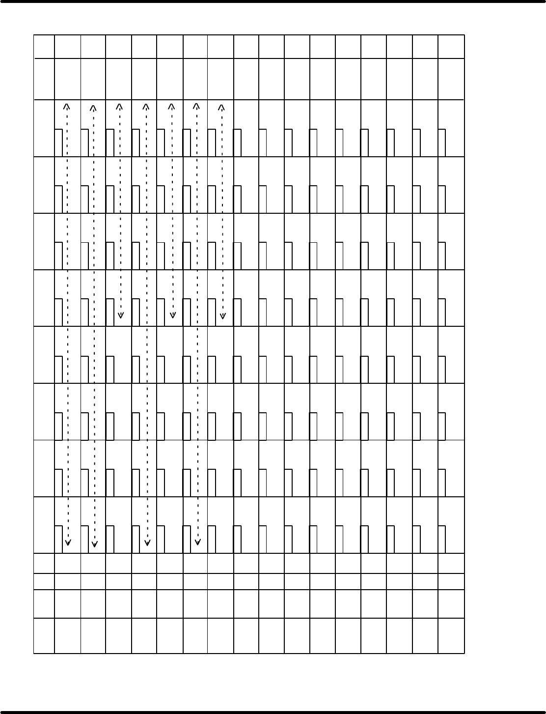
8.8 Monitoring I/O Signals
SERVICE MANUAL
8.8−14
DA3SEC−85−520−A0
ADDRESS LABEL
BLK DEV
7bit 6bit 5bit 4bit 3bit 2bit
1 bit 0 bit COMMENT
7014 0
7014 1
7014 2
7014 3
7014 4
7014 5
7014 6
7014 7
7014 8
7014 9
7014 A
7014 B
7014 C
7014 D
7014 E
7014 F
60
60
60
60
60
60
60
60
6 100
7
17
27
37
47
57
67
77
107
117
127
137
147
157
167
177
16
26
36
46
56
66
76
106
116
126
136
146
156
166
176
5
15
25
35
45
55
65
75
105
115
125
135
145
155
165
175
6 0
171
161
151
141
131
111
121
51
61
71
101
1
11
21
31
41
10
20
50
60
30
40
70
110
120
100
140
150
130
170
160
3
13
23
33
43
53
63
73
103
113
123
133
143
153
163
173
162
2
12
22
32
42
52
62
72
102
112
122
132
142
152
172
4
14
24
34
44
54
64
74
104
114
124
134
144
154
164
174
Link Table−5 RH5
6 100
6 100
6 100
6 100
6 100
6 100
6 100
Invalid
command
X80
X40
X20
X10
X8
X4
X2
X1
X1
X100
X1
X100
X1
X 100
X2
X 200
X2
X 200
X2
X 200
X4
X 400
X4
X 400
X4
X 400
X8
X 800
X8
X 800
X8
X 800
X10
X10
X10
X20
X20
X20
X40
X40
X40
X80
X80
X80
T command
G command
M command
V command
V command
T command
M command
T command
G command
M command
V command
M command
T command
V command
V command
V command
Component select SEQ m MAIN
8.8 Monitoring I/O Signals
SERVICE MANUAL
RH5
8.8−15
DA3SEC−85−520−A0
ADDRESS LABEL
BLK DEV
7bit 6bit 5bit 4bit 3bit 2bit
1 bit 0 bit COMMENT
7015 0
7015 1
7015 2
7015 3
7015 4
7015 5
7015 6
7015 7
7015 8
7015 9
7015 A
7015 B
7015 C
7015 D
7015 E
7015 F
207
217
227
237
247
257
267
277
307
317
327
337
347
357
367
377
216
226
236
246
256
266
276
306
316
326
336
346
356
366
376
205
215
225
235
245
255
265
275
305
315
325
335
345
355
365
375
206
200
371
361
351
341
331
31 1
321
251
261
271
301
201
211
221
231
241
210
220
250
260
230
240
270
310
320
300
340
350
330
370
360
203
213
223
233
243
253
263
273
303
313
323
333
343
353
363
373
362
202
212
222
232
242
252
262
272
302
312
322
332
342
352
372
204
214
224
234
244
254
264
274
304
314
324
334
344
354
364
374
Link Table−6 RH5
6 200
6 200
6 200
6 200
6 200
6 200
6 200
6 200
6 300
6 300
6 300
6 300
6 300
6 300
6 300
6 300
X2
X1
X1
X 100
X1
X 100
X1
X100
X2
X 200
X2
X 200
X2
X 200
T command
G command
M command
V command
M command
T command
V command
V command
V command
X8
X4
X4
X4
X400
X4
X400
X8
X8
X 800
X8
X 800
V command
T command
M command
X4X8
X10
T command
G command
M command
V command
X10
X10
X10
X80
X40
X20
X20
X20
X20
X40
X40
X40
X80
X80
X80
iNVALID
COMMAND
At the guide pin recognition: (1) Command valid, (2) Insert prohibit command, (3) Insert direction Y command (TXX2), (4) Head speed low (T2XX), (5) Guide pin command (V2X)
Insertion SEQ m MAIN