Q170226E01.pdf - 第203页
− Measuring in progress − RH5 5.32 Setting Offset V alues SERVICE MANUAL 5.32−8 DA3SEC−83−9Q0−A0 Automatic camera measuring (X direction) 1. Return to the block select screen. x Press ESC. 2. Select Automatic Camera Offs…
TH−LV
5.32 Setting Offset Values
SERVICE MANUAL
RH5
5.32−7
DA3SEC−83−9Q0−A0
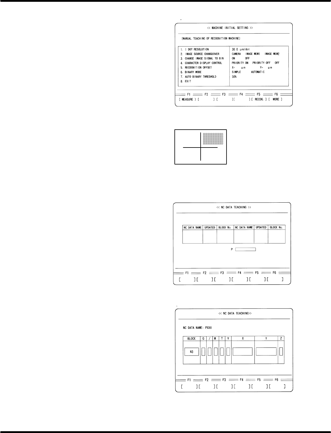
10. Check the threshold level on the recognition
monitor.
x Press ESC.
x Press F1. (MEASURE)
x Press F5.
x Make sure that TH−LV (threshold level) on
the recognition monitor is not less than
140.
If TH−LV is below 140, check the settings
of SW1 and SW2 on the camera. See “2.
Camera Installation” on page 6−32.4.
(Teli camera only)
11. Select teaching mode and choose the NC
data created for adjustment.
x Press ESC three times.
x Press F6. (MORE)
x Press REQ.
x Press F3 (NC DATA TEACHING)
x Move the cursor to the data for adjustment
using npkeys.
x Press ENTER.
x Press F1 (YES).
12. Move the XY table to the insertion position
of N3 block in the NC data.
x Move the cursor to N3 block using np
keys.
x Press ENTER.
x Press F1 (MOVE).
− Measuring in progress −
RH5
5.32 Setting Offset Values
SERVICE MANUAL
5.32−8
DA3SEC−83−9Q0−A0
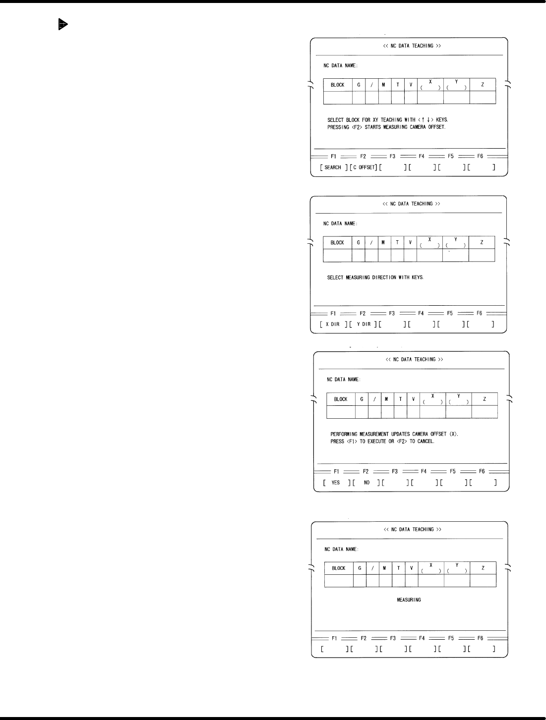
Automatic camera measuring
(X direction)
1. Return to the block select screen.
x Press ESC.
2. Select Automatic Camera Offset Measuring
x Press F2 (C OFFSET)
3. Select the measuring direction.
x Press F1 (X DIR).
4. Execute measuring.
x Press F1.
− Measuring completed −
5.32 Setting Offset Values
SERVICE MANUAL
RH5
5.32−9
DA3SEC−83−9Q0−A0
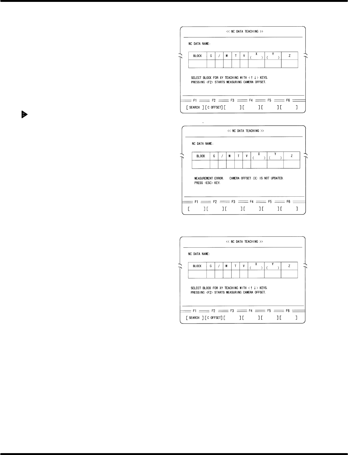
Supplemental remarks
1. After measuring is completed, camera offset
(X) will be automatically overwritten.
2. If a measuring error occurs, a message as in
the left screen appears.
3. Return to the block setting screen.
x Press ESC.
4. Make sure that the insertion hole is not blocked
and repeat the operation from step 2.