Q170226E01.pdf - 第209页
RH5 5.32 Setting Offset V alues SERVICE MANUAL 5.32−14 DA3SEC−83−9Q0−A0 7. Move the XY table to the insertion position of N3 block in the NC data. x Move the cursor to N3 block using np keys. x Press ENTER. x Press F1 (M…
5.32 Setting Offset Values
SERVICE MANUAL
RH5
5.32−13
DA3SEC−83−9Q0−A0
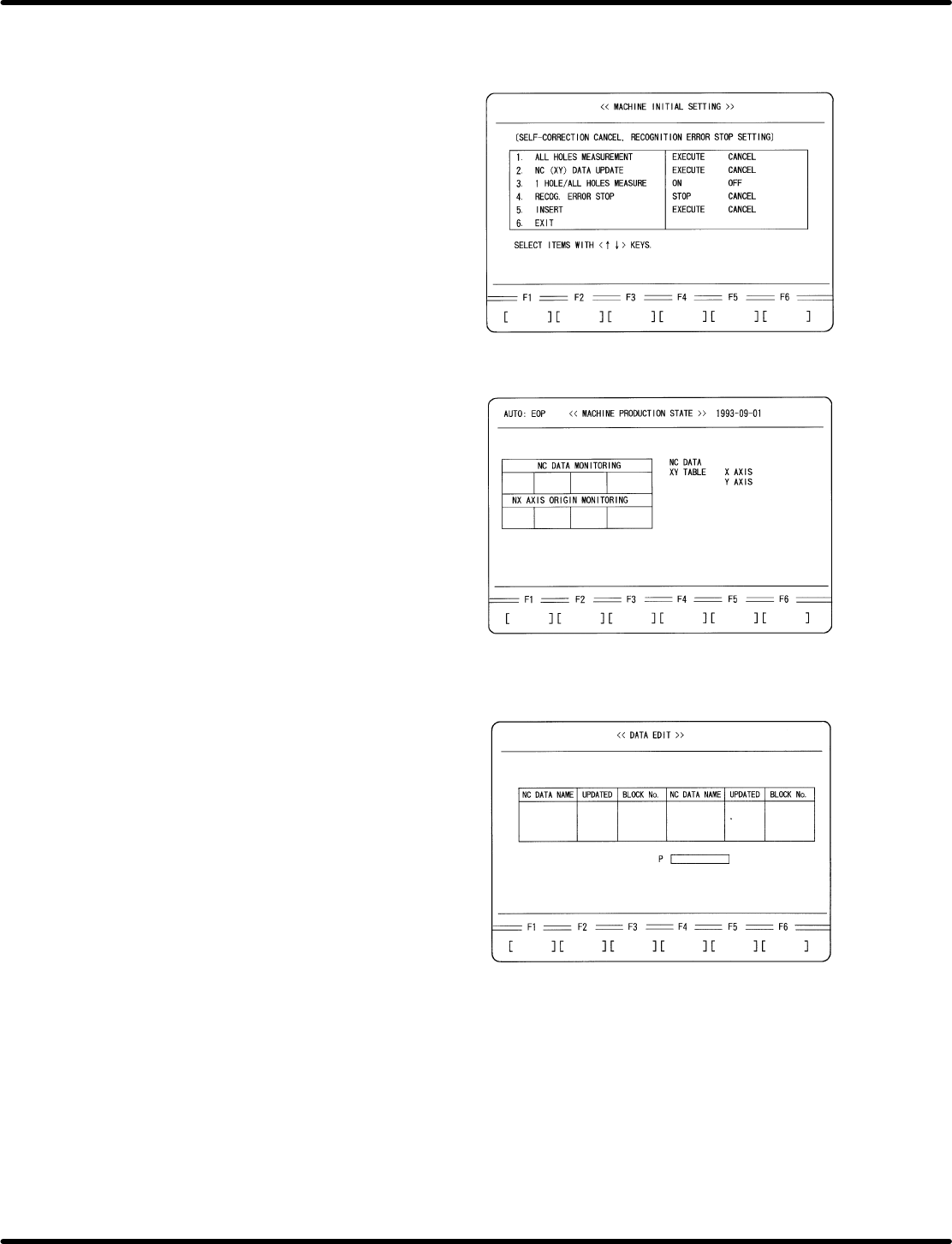
4. Cancel insertion.
x Press ESC three times.
x Press F6 (MORE).
x Press F1 (MACHINE INITIAL DATA).
x Press F6 (MORE) twice.
x Press F2 (SELF−CORRECTION
CANCEL).
x Set the following data:
3. 1 HOLE/ALL HOLES MEASURE−
MENT: OFF
5. INSERT CANCEL
5. Perform recognition in AUTO mode
(Overwrite NC data)
x Press ESC twice.
x Press F6 (MORE).
x Press AUTO.
x Press EOP.
x Press START.
6. Change to MANUAL mode, choose teaching
mode and select the NC data created for
adjustment.
x Press MANU.
x Press 1 BLK.
x Press F3 (NC DATA TEACHING).
x Move the cursor to the name of NC data for
recognition adjustment using npkeys.
x Press ENTER.
x Press F1 (YES).
RH5
5.32 Setting Offset Values
SERVICE MANUAL
5.32−14
DA3SEC−83−9Q0−A0
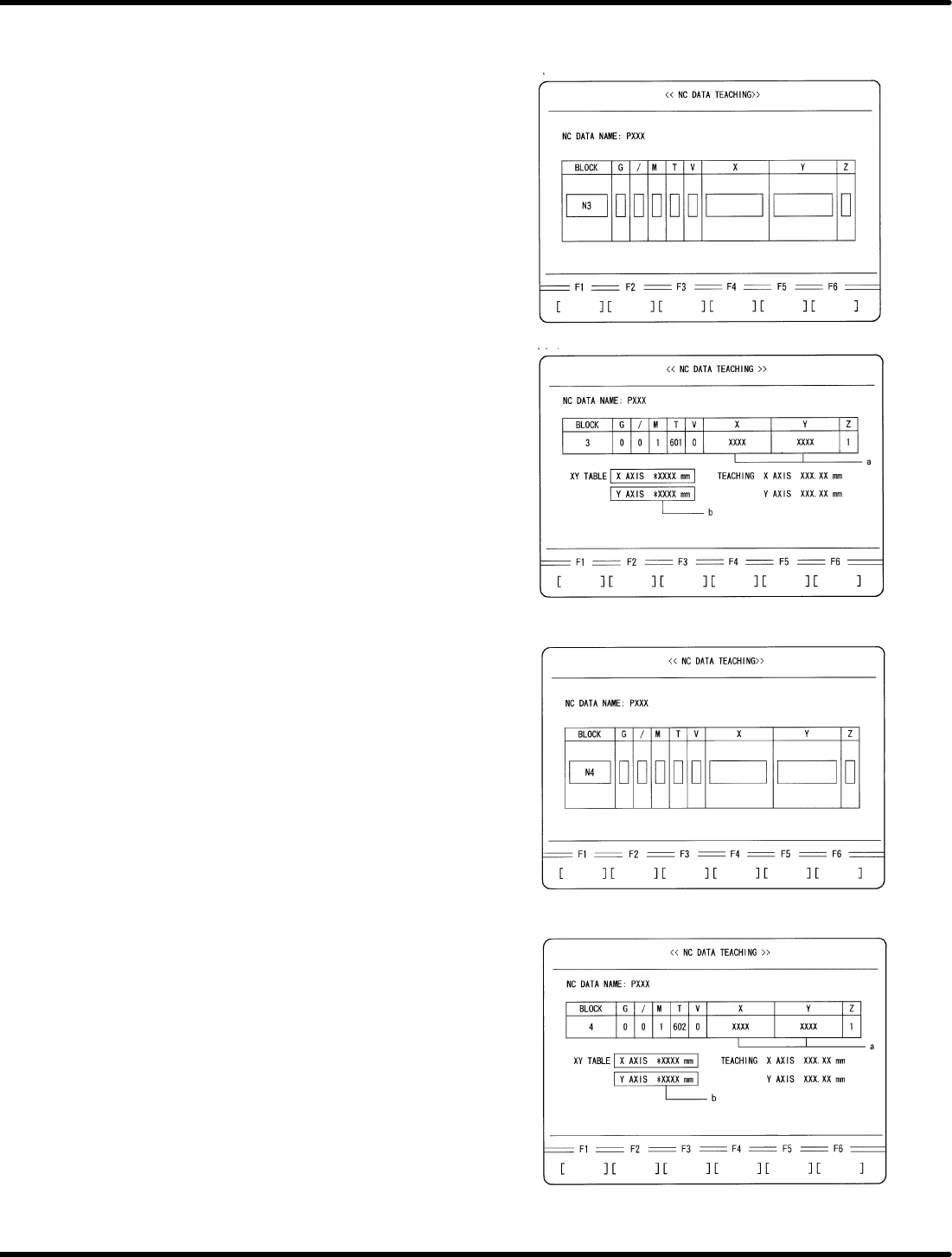
7. Move the XY table to the insertion position
of N3 block in the NC data.
x Move the cursor to N3 block using np
keys.
x Press ENTER.
x Press F1 (MOVE).
8. Check the difference between XY
coordinate (a) and XY table displacement
(b).
x Compare the XY table coordinate (a) and
the XY table displacement (b) written
down in 3. Camera Installation Position
Adjustment (6.32−5 (5)). Make sure that
the difference between these values is
within r0.03 mm.
x Check if the guide pin has been aligned
with the center of the board hole.
9. Move the XY table to the insertion position
of N4 block in the NC data.
x Press ESC.
x Move the cursor to N3 block using np
keys.
x Press ENTER.
x Press F1 (MOVE)
10. Check the difference between XY
coordinate (a) and XY table displacement
(b).
x Compare the XY table coordinate (a) and
the XY table displacement (b) written
down in 6.32−11 (3). “Automatic Camera
Offset Measuring (Y Direction)”.
Make sure that the difference between
these values is within r 0.03 mm.
x Check if the guide pin has been aligned
with the center of the board hole.
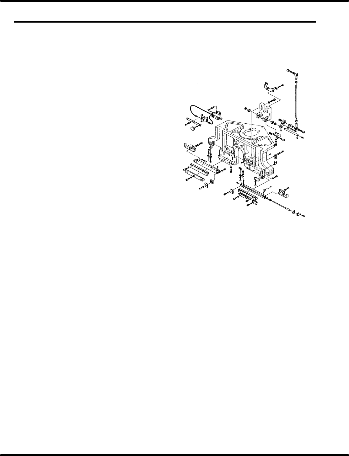
5.33 Lead Cutter and Tape Cutter Stroke Adjustment
SERVICE MANUAL
RH5
5.33−1
DA3SEC−83−9R0−A0
5.33 Lead Cutter and Tape Cutter Stroke Adjustment
DA3SEC−83−9R0−A0
Sentence No.
When to perform
x When cutting errors occur.
Required tools
x Lever−operated dial gauge
x Allen wrench
Preparations
x Move the feeder carriage to a position
where the cutter blade can be removed
easily from the rear of the machine.
x Remove the cutter blade and replace
with new ones (lead cutter, tape cutter).