Q170226E01.pdf - 第45页
RH5 2.3 Sensor Layout SERVICE MANUAL 2.3−2 DA3SEC−82−070−B0 X−Y T ABLE − PHOTO Y axis Y axis slow down PH20 Y axis safety input SW X axis safety input SW Y axis − limit PH18 Y axis origin PH21 Y axis + limit PH16 Ya x i …
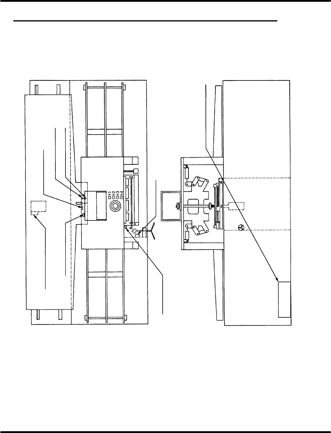
2.3 Sensor Layout
SERVICE MANUAL
RH5
2.3−1
DA3SEC−82−070−B0
2.3 Sensor Layout
DA3SEC−82−070−B0
Sentence No.
Anvil swivel forward (0123)
Anvil swivel reverse (0124)
Feed component detection
(PH01)
Component end
detection (0073)
Feed forward detection
(0125)
Feed reverse detection
(0126)
Clamp (0131)
Handle (0047)
Distortion gauge CH1 (0064)
CH2 (0065)
CH3 (0066)
Power source
panel
RH5
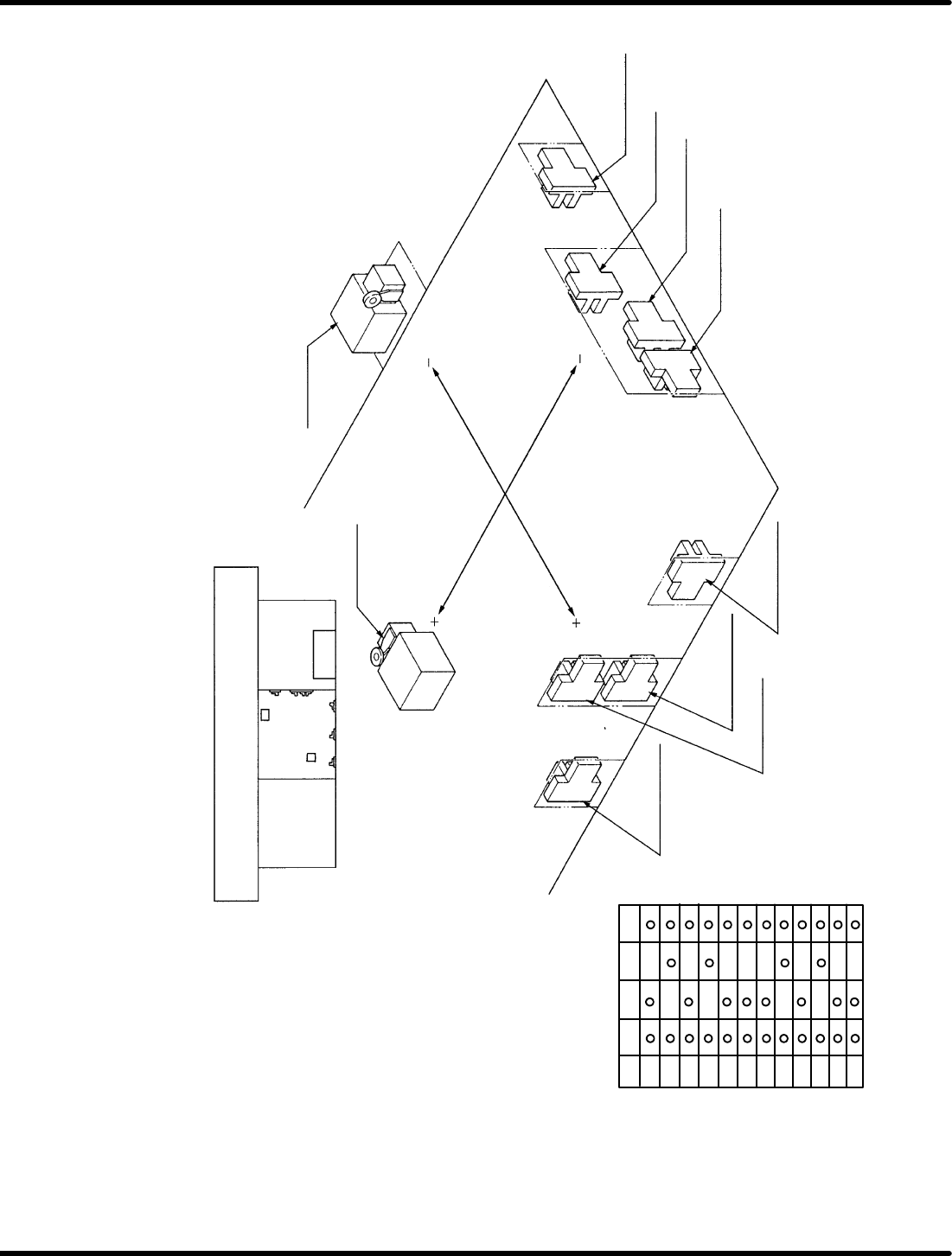
2.3 Sensor Layout
SERVICE MANUAL
2.3−2
DA3SEC−82−070−B0
X−Y TABLE
− PHOTO
Y axis
Y axis slow down
PH20
Y axis safety
input SW
X axis safety
input SW
Y axis − limit
PH18
Y axis origin
PH21
Y axis + limit
PH16
Yaxis
Photoelectric sensor
connection terminal
PH10
PH11
PH12
PH13
PH14
PH15
PH16
PH17
PH18
PH19
PH20
PH21
1(−)
2(OUT) 3(OUT)
4(+)
2 shade ON
3 shade ON
+ PHOTO
Main control
panel
Xaxis
X axis slow down
PH14
X axis + limit
PH10
X axis origin
PH15
X axis − limit
PH12
+ Photo
X axis
ORG
Photo
− Photo
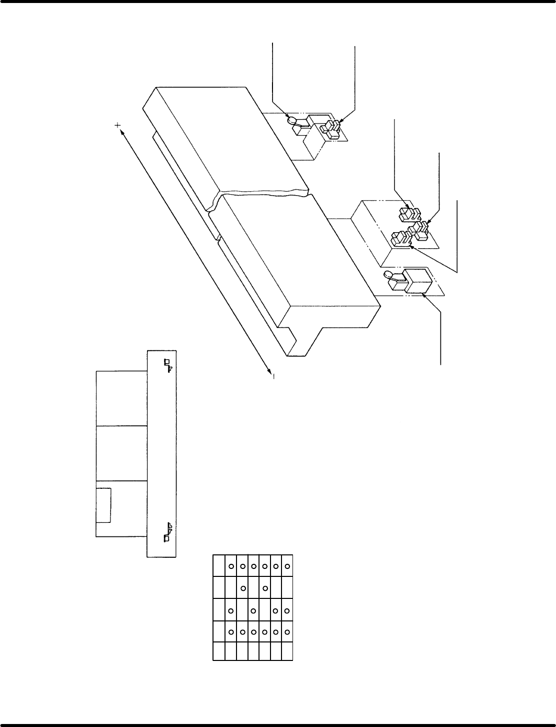
2.3 Sensor Layout
SERVICE MANUAL
RH5
2.3−3
DA3SEC−82−070−B0
Main control
panel
Zaxis−PHOTO
Machine rear side
Zaxis
Zaxis+safety
input SW
Z axis + limit
PH22
Zaxisslowdown
PH26
Zaxisorigin
PH27
Z axis − limit PH24
Zaxis−safety
input SW
Photoelectric sensor
connection terminal
PH22
PH23
PH24
PH25
PH26
PH27
1(−)
2(OUT) 3(OUT)
4(+)
2 shade ON
3 project ON
Zaxis+PHOTO