Q170226E01.pdf - 第195页
Set screw B Set screw A Acrylic plate LED board Acrylic plate holder Collar Bolt LED bracket RH5 5.31 Recognition Camera Lens Lamp Replacement and Adjustment SERVICE MANUAL 5.31−2 DA3SEC−83−9P0−A0 Acrylic plate replaceme…
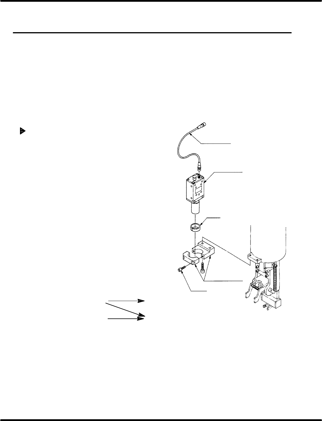
Camera cable
Camera unit
Collar
Bolt A
Camera bracket
Camera maker
Teil
(X00C86322)
NEC
(X00K84903)
Camera cable
Type L
(X00C83409)
Straight
(X00K84905)
Recognition board
Old
(X984−204)
New
(X984−211)
Compatibility: Camera cable and recognition board
5.31 Recognition Camera Lens Lamp Replacement and Adjustment
SERVICE MANUAL
RH5
5.31−1
DA3SEC−83−9P0−A0
5.31 Recognition Camera Lens Lamp Replacement and
Adjustment
DA3SEC−83−9P0−A0
Sentence No.
When to perform
x After replacing the camera lens.
x When the guide pin does not pass through
the insertion hole.
Required tools
x Allen wrench
Camera replacement
1. Disconnect the camera cable from the
camera unit.
2. Loosen bolt A (x 2) and remove camera
unit (with lens) from the camera bracket.
3. Replace camera unit.
4. Set camera unit (with lens) on the camera
bracket so that the labels facing forward.
Then, tighten bolt A (x 2).
5. Connect the camera cable to camera unit.
=CHECK=
Do not soil the camera lens or CCD
sensor.
=REFERENCE=
X984−211: If required for jumper
resetting, refer to 8.3.3.
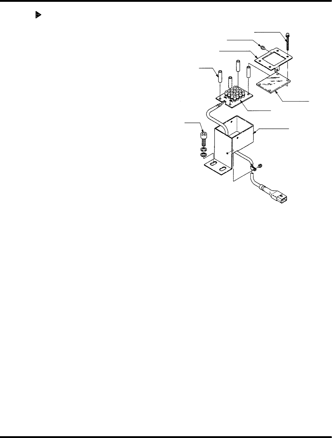
Set screw B
Set screw A
Acrylic plate
LED board
Acrylic plate
holder
Collar
Bolt
LED bracket
RH5
5.31 Recognition Camera Lens Lamp Replacement and Adjustment
SERVICE MANUAL
5.31−2
DA3SEC−83−9P0−A0
Acrylic plate replacement
1. Loosen set screw A (x 2) and B (x 4).
2. Detach plate holder to remove acrylic
plate.
3. Install a new acrylic plate and attach the
plate holder.
4. Tighten set screws A (x 2) and B (x 4).
=REFERENCE=
When changing the LED board,
replace the whole unit.
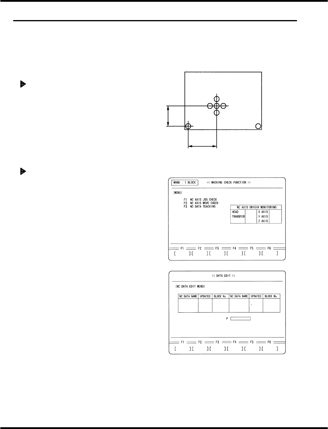
Origin board for recognition adjustment
67.5 mm
140.0 mm
ORG
5.32 Setting Offset Values
SERVICE MANUAL
RH5
5.32−1
DA3SEC−83−9Q0−A0
5.32 Setting Offset Values
DA3SEC−83−9Q0−A0
Sentence No.
When to perform
x After replacing the recognition camera.
Preparation
x Origin board for recognition adjustment
Preparations
1. Prepare an origin board for recognition
adjustment.
2. Set the widths of XY table, loader and
unloader to that of the prepared board.
3. Set a reference pin. (I4.0)
Creating NC data
1. Turn power ON.
x Press OPERATION READY.
2. Call up the NC DATA EDIT (CREATE)
screen.
x Press REQUEST.
x Press F2 (DATA EDIT).
x Press F1 (NC DATA).
x Press F1 (CREATE).