Q170226E01.pdf - 第43页
RH5 2.2 Electronic Component Insertion and Related Operations SERVICE MANUAL 2.2−2 DA3SEC−82−260−A0 = MEMO =
2.2 Electronic Component Insertion and Related Operations
SERVICE MANUAL
RH5
2.2−1
DA3SEC−82−260−A0
2.2 Electronic Component Insertion and Related
Operations
DA3SEC−82−260−A0
Sentence No.
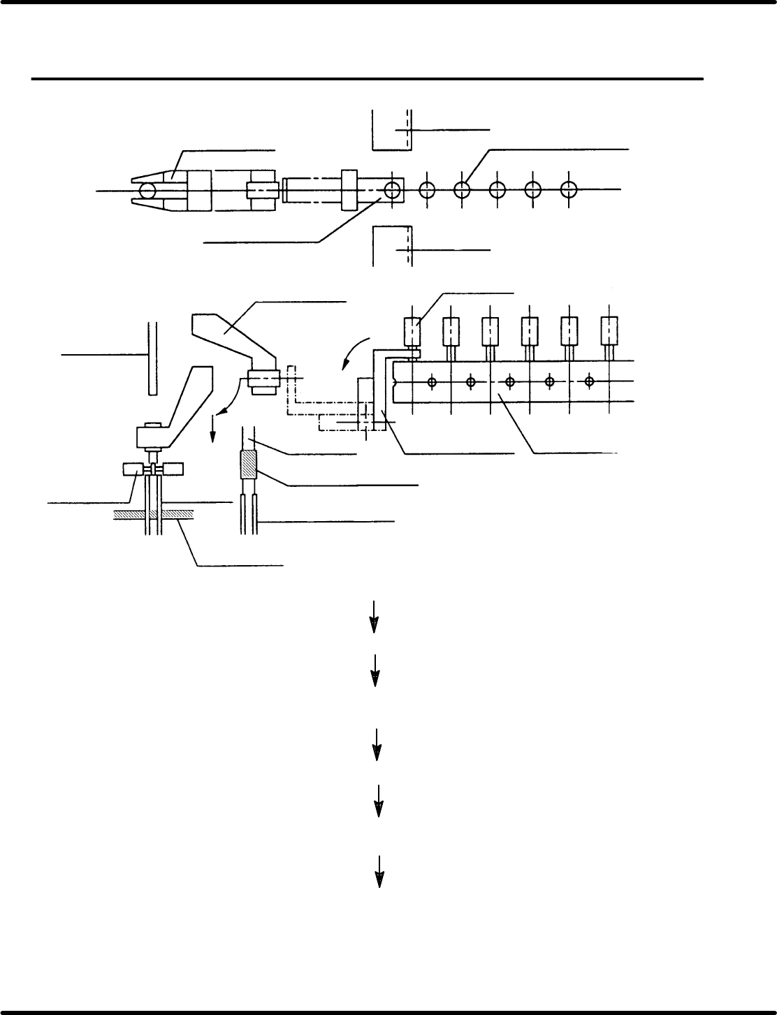
(7) Cutter
(1) Electronic component
(taped)
(2) Transfer chuck
(7) Cutter
(1) Electronic
component
(1) Electronic component
(3) Insertion chuck
(3) Insertion chuck
(4) Pusher
(4) Pusher
Guide chuck
(5) Lead guide pin
(6) PC board
(5) Lead
guide pin
(A)
(B)
(C)
(2) Transfer chuck
(8) Base tape
Electronic component (1) is fed by one pitch and held with transfer
chuck (2).
Leads and base tape (8) are cut by cutter (7).
Transfer chuck (2) rotates in the direction of arrow (A) and the
component is transferred to insertion chuck (3).
Insertion chuck (3) rotates in the direction of arrow (B) and lowers
in the direction of arrow (C).
Electronic component (1) is held by pusher (4) and lead guide pin
(5), and is inserted into holes in PC board (6).
Component leads are cut and clinched so that the component is
fixed on PC board (6).

RH5
2.2 Electronic Component Insertion and Related Operations
SERVICE MANUAL
2.2−2
DA3SEC−82−260−A0
= MEMO =
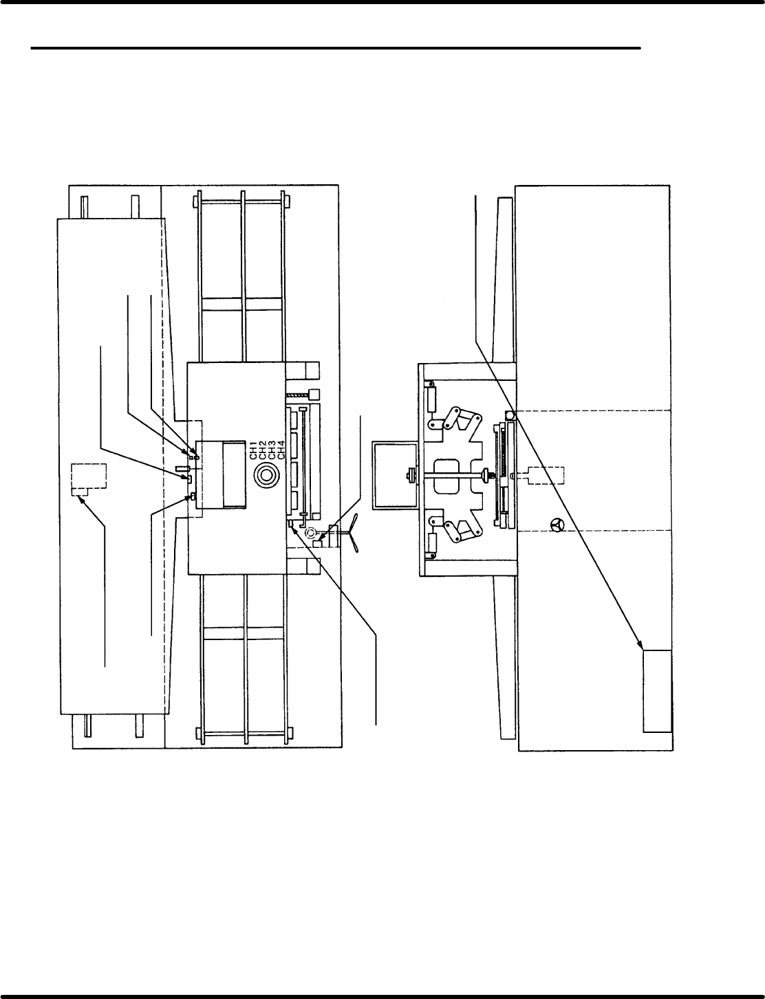
2.3 Sensor Layout
SERVICE MANUAL
RH5
2.3−1
DA3SEC−82−070−B0
2.3 Sensor Layout
DA3SEC−82−070−B0
Sentence No.
Anvil swivel forward (0123)
Anvil swivel reverse (0124)
Feed component detection
(PH01)
Component end
detection (0073)
Feed forward detection
(0125)
Feed reverse detection
(0126)
Clamp (0131)
Handle (0047)
Distortion gauge CH1 (0064)
CH2 (0065)
CH3 (0066)
Power source
panel