Q170226E01.pdf - 第359页
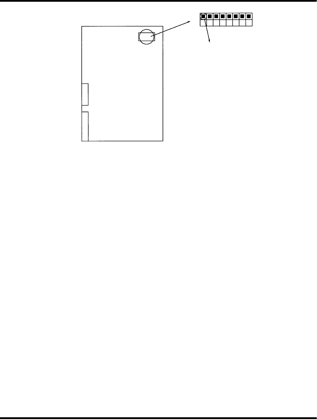
RH5 8.7 CNC Board T able Setting SERVICE MANUAL 8.7−2 DA3SEC−85−510−B0 CN2 1 2 3 456 78 OFF ON DIP−SW1 1−ON 1st pc.

8.7 CNC Board Table Setting
SERVICE MANUAL
RH5
8.7−1
DA3SEC−85−510−B0
8.7 CNC Board Table Setting
DA3SEC−85−510−B0
Sentence No.
Replacing CNC board and changing the setting
1. Turn ON the DIP−SW1 No.1 on the CNC board.
2. Set the CNC board to P−791 to turn ON the power supply.
3. The CNC starts up with NG. Turn OFF the power supply.
4. Turn OFF the DIP−SW1 No.1 on the CNC board.
5. After setting the CNC board to P−791, turn ON the power to the machine to change the CNC settings
automatically within approx. 30 sec.
=CHECK=
When setting the CNC board on the ZR axis side for 2−division machines, set the DIP−SW1 to
“OFF” in step 1 and set to “ON” in step 4 above.
When setting the CNC board other than described models, follow the same steps as described above.
(Be sure to check the double under line columns in each setting table.)
Changing the setting of CNC table only
1. Turn ON the power to the machine.
2. Press “REQ” − “F6” (MORE) − “F2” (MONITORING) on the monitor screen.
3. Press “F3” (MEMORY). (”ADDR” is displayed at the right bottom on the monitor screen.)
4. Input the setting value in ADDR according to the table setting list.
Ex. When “01” of usual max. speed 7901 for X axis 704050H is 02:
5. Input 74050 in ADDR to press “ENTER”.
(The values from 0 to F will be displayed in the same manner as the table setting list.)
6. At present, No. 7 of 74050 is 02, change to 01.
7. Press “F1” (CPU−286) five times.
DATA appears below ADDR.
8. Enter 74057 in ADDR and press “ENTER”.
(The cursor moves to DATA position.)
9. Entrer “01” in DATA to press “ENTER”. (02 of No. 7 is changed to 01 on the monitor)
10. Next, input a command for changing the table.
Input 74042 in ADDR of X axis and press “ENTER”.
11. Enter “80” in DATA to press “ENTER”.
12. Next, input an execution command for changing the table.
Enter 74FFE in ADDR of X axis to press “ENTER”.
13. Enter FF in DATA to press “ENTER”.
14. Wait approx. one minute until the value is automatically updated.
=CHECK=
After setting the table, do not turn OFF the machine until table value is updated.
After changing the settings, turn OFF the machine once and turn it back ON for safety reason to
make sure the setting values are changed.
RH5
8.7 CNC Board Table Setting
SERVICE MANUAL
8.7−2
DA3SEC−85−510−B0
CN2
1 2 3 456 78
OFF
ON
DIP−SW1
1−ON 1st pc.
8.7 CNC Board Table Setting
SERVICE MANUAL
RH5
8.7−3
DA3SEC−85−510−B0
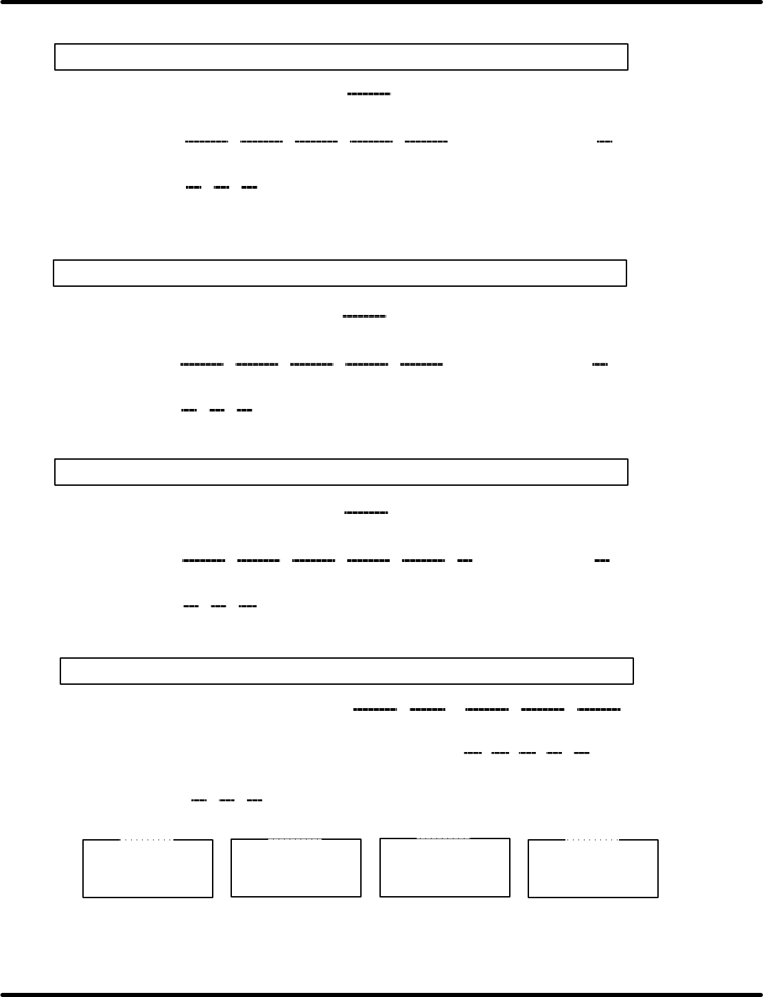
RH5(M) CNC board setting list
(X axis)
0123456789ABCDEF
74050
74060
74070
DD 02
8A 02 8A 02 64 00 0A 00
16 00
08 00 F4 01 0A 00 A7 00 2F 2D 2D 40 40 40
20
60 28 00
(Usual max. speed)
(Jog high
speed)
(Jog low
speed)
(Origin
return)
(Slow down)
(Servo lock
speed)
(Normal
acceleration)
(Jog
acceleration)
(Origin
return
acceleration)
(Servo
lock)
(Emergency
stop)
(Y axis)
0123456789ABCDEF
740D0
740E0
740F0
(Z axis)
0123456789ABCDEF
74150
74160
74170
(H axis)
0123456789ABCDEF
741D0
741E0
741F0
16 00 08 00 64 01 04 00 64 00 8C
C2 B9 74 80 64
20
40 80 00
Max. speed (0.36) (0.45) (0.6) (0.29) (0.33)
Acceleration
CA 01 6E 01130138 02 F4 01
(0.36) (0.45) (0.6) (0.29) (0.33)
DD 02 8A 02 8A 02 64 00 0A 00
16 00
08 00 F4 01 0A 00 A7 00 2F 2D 2D 40 40 40
20
60 28 01
(Usual max. speed)
(Jog high
speed)
(Jog low
speed)
(Origin
return)
(Slow down)
(Servo lock
speed)
(Normal
acceleration)
(Jog
acceleration)
(Origin
return
acceleration)
(Servo
lock)
(Emergency
stop)
FA 00 4D 01 4D 01 2C 01 2C 01
16 00
08 00 EE 00 08 00 A7 00 50 60 60 80 80 40
55
86 C8 02
(Usual max. speed)
(Jog high
speed)
(Jog low
speed)
(Origin
return)
(Slow down)
(Servo lock
speed)
(Normal
acceleration)
(Jog
acceleration)
(Origin
return
acceleration)
(Servo
lock)
(Emergency
stop)
74042 o 80
740FFE o 11
X axis
740C2 o 80
740FFE o 11
Y axis
74142 o 80
740FFE o 11
Z axis
741C2 o 80
740FFE o 11
H axis