Q170226E01.pdf - 第122页
Lever−operated dial gauge Insertion chuck Surface of the insertion head Guide rail Spring Parallelism: 0.05/20 − 30 mm 5.6 Insertion Head Guide Parallelism Check and Adjustment SERVICE MANUAL RH5 5.6−1 DA3SEC−83−8N0−A0 5…
RH5
5.5 Insertion Head Guide Parallelism Check and Adjustment
SERVICE MANUAL
5.5−4
DA3SEC−83−8M0−A0
Adjusting parallelism (3)
(Adjusting the X stopper)
1. Using the hand wheel, set the digital
sequence timer to 210q.
2. Press the X stopper against the stage (1)
and secure it with bolts.
=REFERENCE=
Too strong pressing the stopper will
cause the low accuracy.
3. Check that the accuracy is within 0.04 mm
again.
Adjusting parallelism (4)
(Adjusting the Y stopper)
1. Using the hand wheel, set the digital
sequence timer to 90q.
2. Press the Y stopper against the stage (1)
and secure it with bolts.
=REFERENCE=
Too strong pressing the stopper will
cause the low accuracy.
3. Check that the accuracy is within 0.04 mm
again.
Adjusting
bolt
Lever−operated dial
gauge
X stopper
X stopper
Stage (1)
(NG) (OK)
Adjusting
bolt
Lever−operated dial
gauge
Y stopper
Y stopper
Stage (1)
Parallelism: 0 − 0.04 mm
Parallelism: 0 − 0.04 mm
Lever−operated dial
gauge
Insertion chuck
Surface of the
insertion head
Guide rail
Spring
Parallelism:
0.05/20 − 30 mm
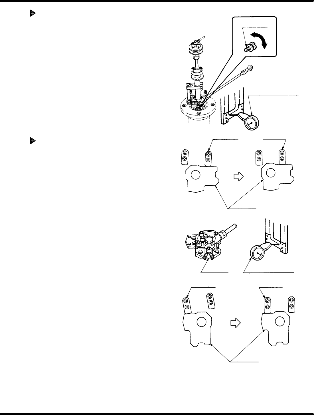
5.6 Insertion Head Guide Parallelism Check and Adjustment
SERVICE MANUAL
RH5
5.6−1
DA3SEC−83−8N0−A0
5.6 Insertion Head Guide Parallelism Check and
Adjustment
DA3SEC−83−8N0−A0
Sentence No.
When to perform
x When parts leads do not readily
slip into the guide chuck.
x When insertion errors occur
frequently.
x Allen wrench
x Box wrench
x Lever−operated dial gauge
Required tools
Parallelism check
1. Remove the spring from the insertion
head.
2. Set the machine to manual mode and turn
OFF the HEAD SWIVEL LOCK. Turn the
hand wheel until the cam shaft is at the 0q
position on the digital sequence timer.
3. Attach the lever−operated dial gauge to
the guide rail (fixed side) on the X−Y
table.
4. Set the measuring needle on the side
surface of the insertion head.
5. Move the X−Y table in the X direction by
hand.
=CHECK=
If sliding the X− Y table by hand, make
sure the table does not slip in the Y
direction.
6. Check parallelism of the insertion head
(inserting chuck) against the guide rail is
between 0.05/20 − 30 mm.
RH5
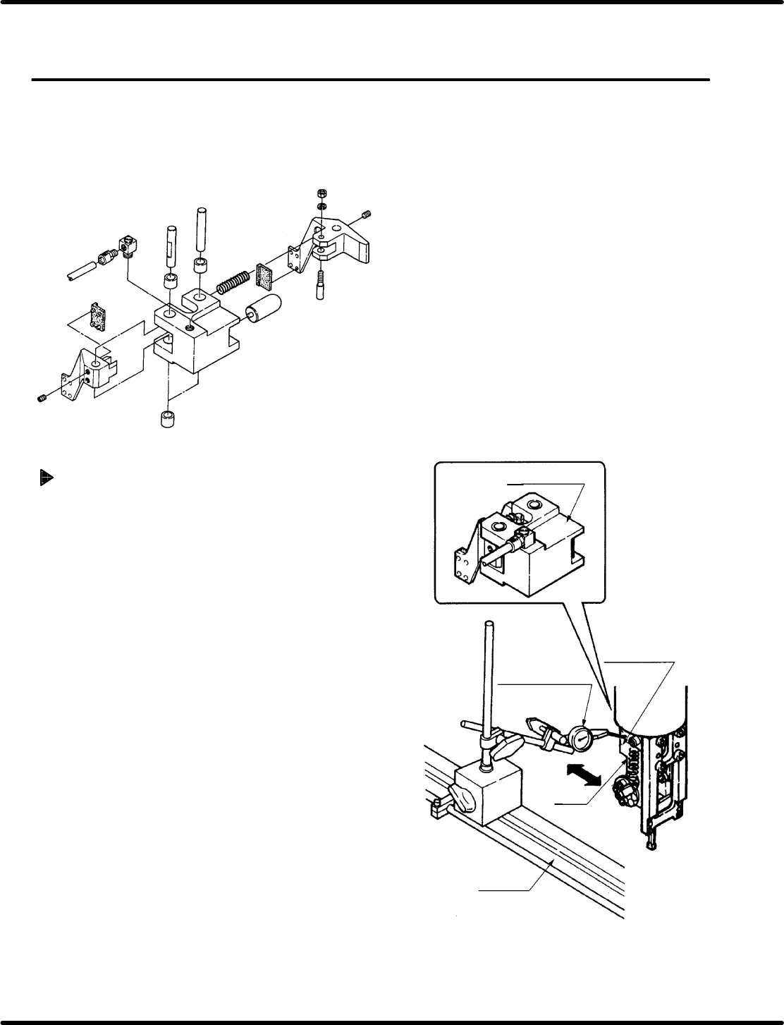
5.6 Insertion Head Guide Parallelism Check and Adjustment
SERVICE MANUAL
5.6−2
DA3SEC−83−8N0−A0
Adjusting parallelism
1. Loosen the bolt on the insertion head drive unit.
Then, while pressing down on the arm by hand,
turn the cam follower guide until the correct
degree of parallelism is obtained.
2. After making adjustment, tighten the arm bolt to
check for the parallelism again.
=CHECK=
Be careful not to change the arm height when
tightening the arm bolt because the arm
moves up/down easily during adjustment.
Cam follower
guide
Arm
Bolt