Q170226E01.pdf - 第243页
6.1 Checking Maintenance Precision SERVICE MANUAL RH5 6.1−6 DA3SEC−89−010−A0 No. Check item Description Illustration Criteria Measured value 25 26 27 28 29 OK/NG Visual check 0t o0 . 0 5m m ******* mm 0t o0 . 0 3m m mm 0…
RH5
6.1 Checking Maintenance Precision
SERVICE MANUAL
6.1−5
DA3SEC−89−010−A0
No.
Check item
Description
Illustration
Criteria
Measured
value
20
Pickup test
Selector rod
clearance setting
To be measured at
210
Bolt
When the guide pin is at
the uppermost position,
move the guide pin upper
cylinder up/down until three
pins are parallel to one
another. Then, set the
clearance 0.3 mm higher
than this position.
M3 x 2
21
22
23
24
mm
0.25 to 0.35 mm
mm
0to0.02mm
mm
0.5to0.7mm
OK/NG
Visual check
OK/NG
Visual check
OK/NG
White marker
check
OK/NG
White marker
check
OK/NG
White marker
check
Bolt
M5 x 1
Bolt
M6 nut x 2
Bolt
M5 x 2
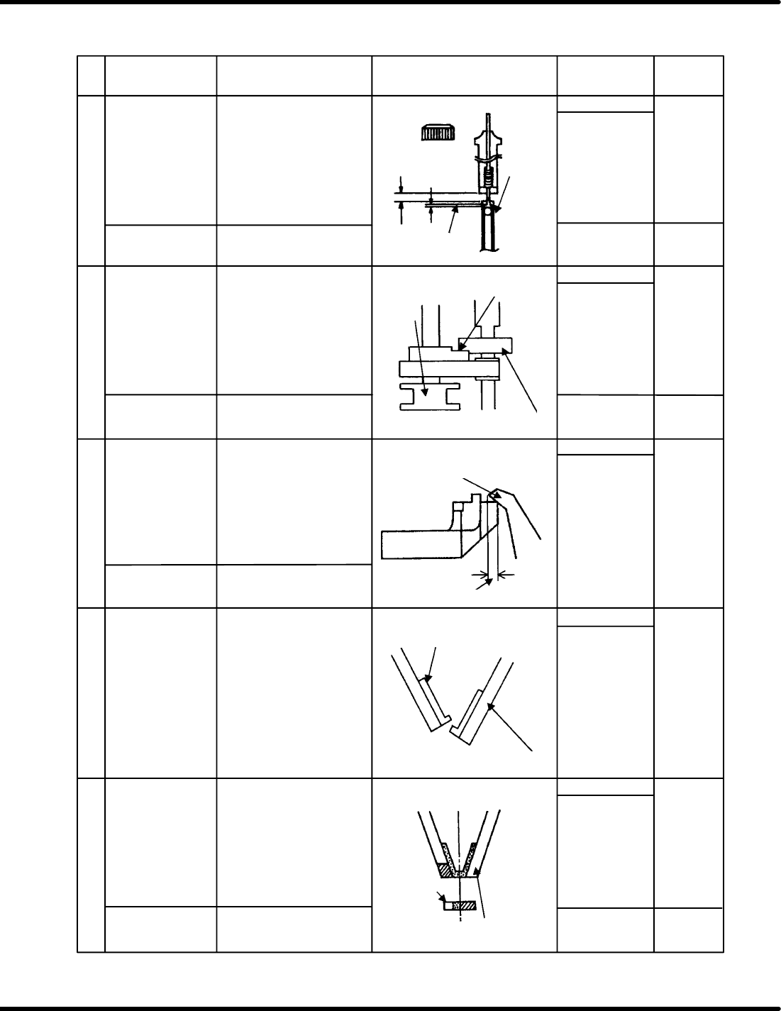
Guide pin upper
stopper setting
To be measured at
210
Measure the clearance
between the guide pin and
stopper when the guide pin
is at the uppermost
position.
Movable blade
stroke
Measure the clearance
between the center lead cut
blade and movable blade at
the maximum stroke
position.
Insertion chuck
closing precision
Ensure that the chuck
rubber is not mispositioned
when the insertion chuck is
closed.
Insertion
chuck/guide chuck
closing center
Check the closing center of
the insertion chuck and
guide chuck at the 230
position.
Uppermost
position
Ensure clearance
here.
Clearance: 0
Stopper
Uppermost
position
Maximum stroke
position
Stroke
Insertion chuck
rubber
Insertion chuck
claw
Guide chuck
Insertion chuck
claw
Thickness gauge
Pin gauge
6.1 Checking Maintenance Precision
SERVICE MANUAL
RH5
6.1−6
DA3SEC−89−010−A0
No.
Check item
Description
Illustration
Criteria
Measured
value
25
26
27
28
29
OK/NG
Visual check
0to0.05mm
*******
mm
0to0.03mm
mm
0to0.03mm
mm
0to0.15mm
mm
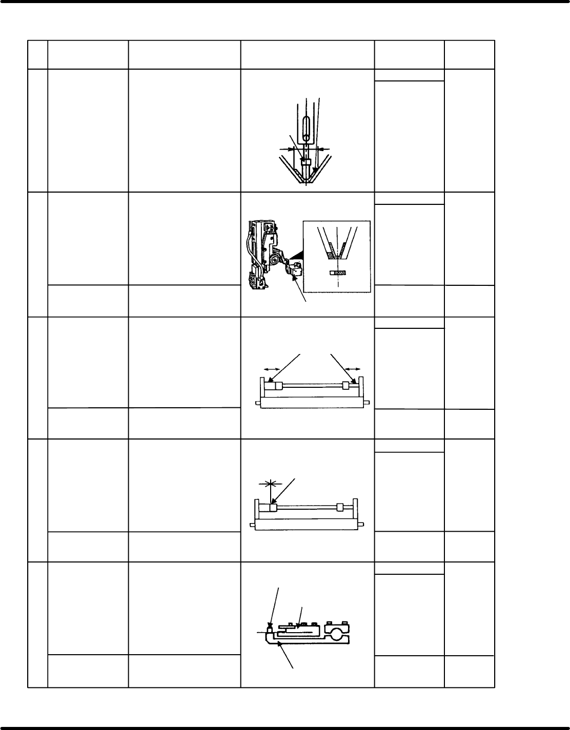
Insertion pusher
and insertion
chuck center
Ensure that the insertion
pusher is aligned with the
insertion chuck.
Insertion pusher
Insertion chuck
rubber
Transfer chuck
Transfer chuck and
insertion chuck
center
To be measured at
90
Bolt
M8 x 4
Check the center of the
transfer chuck and insertion
chuck at the 90 position with
the closing position of the
insertion chuck as the
reference.
(Measure with a 0.2
mm−thickness gauge.)
Pickup test
OK/NG
White marker
check
OK/NG
White marker
check
OK/NG
White marker
check
OK/NG
White marker
check
Pickup test
Pickup test
Pickup test
Bolt
M5 x 1
Bolt
M5 x 2
Bolt M5 x 4
Positioner
positioning
precision
Measure the positioning
precision by checking for
clearance between the
positioner shaft and
bearing.
Clearance
Clearance
Positioning pin
PCB transfer rail
Positioning lever
Positioning lever
height
Positioning lever
installation
precision
Measure the height of the
positioning lever with the
transfer surface of the PCB
transfer rail as the
reference.
Measure the installation
precision by checking for
clearance between the
positioning lever and collar
on the reference side.
RH5
6.1 Checking Maintenance Precision
SERVICE MANUAL
6.1−7
DA3SEC−89−010−A0
No.
Check item
Description
Illustration
Criteria
Measured
value
30
31
32
33
34
mm
0to0.02mm
0.3to0.7mm
*******
mm
0.5to0.7mm
mm
Visual check
OK/NG
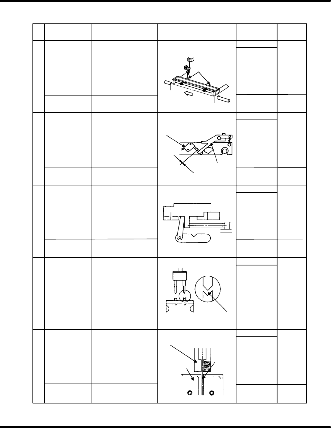
Positioning pin
parallelism
Measure the parallelism by
moving the table in X
direction with the positioning
pin on the left as the
reference.
Positioning pin
Micro−switch
PCB micro−switch
setting
Bolt
M4 hexagonal x 2
Measure the clearance
between the micro−switch
and lever.
Pickup test
OK/NG
White marker
check
OK/NG
White marker
check
OK/NG32.7 Nm
Pickup test
Bolt
M5 x 1
Bolt
M8 x 4
Clearance between
feed pusher and
parts cassette
To be measured at
290
Check the clearance
between the feed pusher
and parts cassette with the
feed pusher protruded.
Bolt
M5 x 4
Lever
OK/NG
White marker
check
Thickness gauge
Right end:
mm
Left end:
Visual check
OK/NG
Thickness gauge
Z axis origin
Feed and cutter
center
Ensure that the center
position of the transfer
chuck and groove of the
parts cassette are matched.
Transfer chuck
Cassette
Center position
must be
matched.
Using the electronic
components whose precision
have been checked by the
taping gauge, cut the lead
manually to check for the
V−cut condition.
Cut condition
* Check only