Q170226E01.pdf - 第153页
RH5 5.16 Replacing Anvil Distortion Gauge SERVICE MANUAL 5.16−4 DA3SEC−83−8YO−A0 6. Cut the lead wire from the distortion gauge and solder it to the gauge terminal. 7. Make sure that the difference of the resistance betw…
5.16 Replacing Anvil Distortion Gauge
SERVICE MANUAL
RH5
5.16−3
DA3SEC−83−8YO−A0
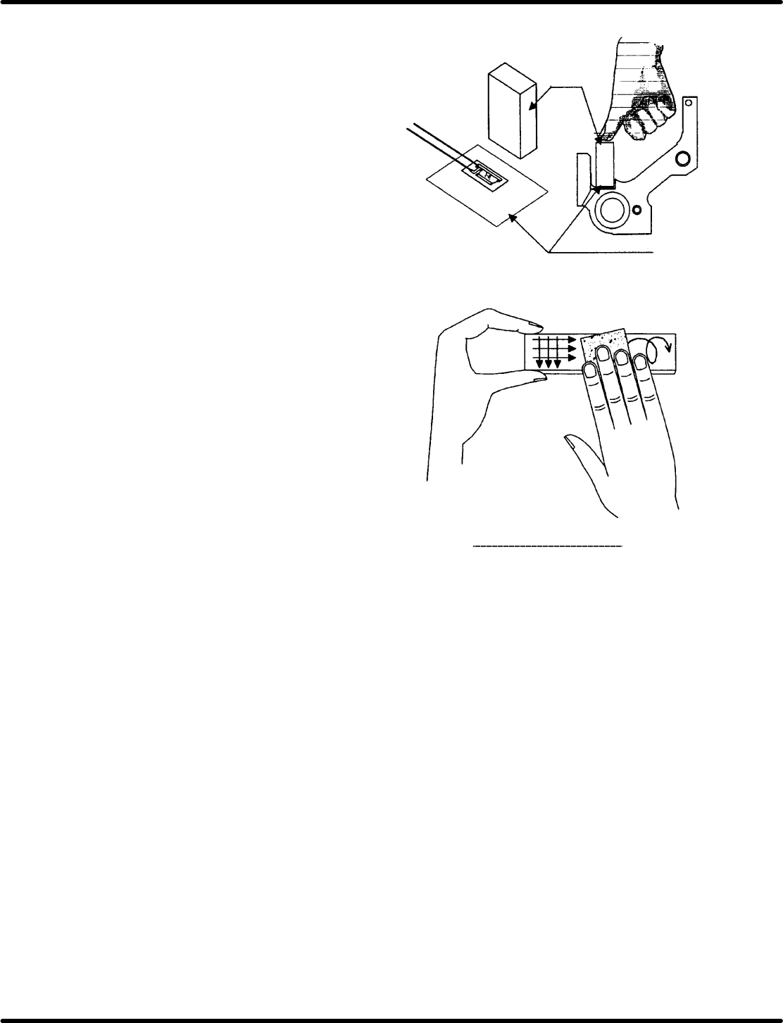
=CHECK=
x Lay a polyethylene sheet under an eraser or
elastic products that can hold the distortion
gauge entirely by hand.
x Don’t perform the mirror finishing on the
attaching surface with a piece of sand
paper. (Finish it crosswise or circularly.)
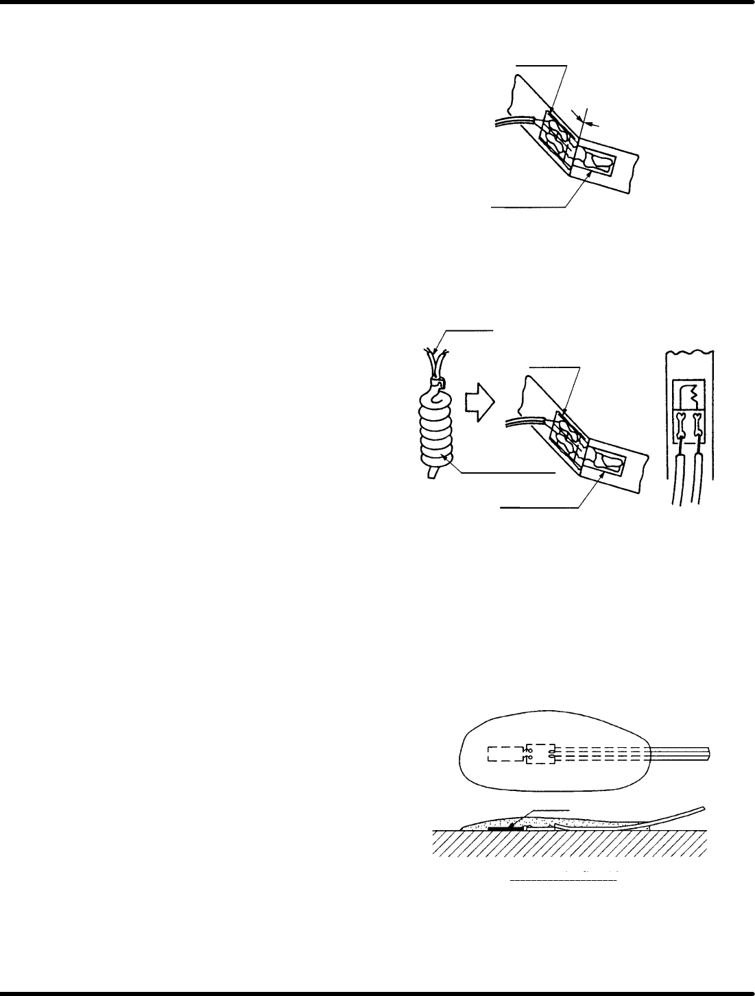
x When attaching the distortion gauge and
gauge terminal, check that no gap is
found between them.
Precautions in handling adhesive
x Take out the adhesive from the container
immediately before attaching the units.
x When attaching the gauge, keep the
pressure between 49.5 and 98.1 KPa.
x Attach the gauge rapidly before the
adhesive is cured by reaction with moisture
in the air.
x After applying adhesive and pressing down
the gauge for more than one minute, it aside
for three or four hours to increase the
adhesive strength before coating.
x After using adhesive, do not leave it in high
temperature environment. (Put it into cold
storage.)
Finishing with a piece of sand
Eraser
Polyethylene sheet
RH5
5.16 Replacing Anvil Distortion Gauge
SERVICE MANUAL
5.16−4
DA3SEC−83−8YO−A0
6. Cut the lead wire from the distortion gauge
and solder it to the gauge terminal.
7. Make sure that the difference of the
resistance between the marking of the
resistor on the package and the measured
value after having been attached is within
r5:.
=REFERENCE=
If the difference is outside the given
range, the distortion gauge was not
attached evenly. When this happens, it
is advised to remove and reattach the
distortion gauge.
8. Solder the lead wire (2 each) of the spiral
tube to the gauge terminal.
=CHECK=
Do not overheat the solder in soldering.
(Use 100V AC/15W soldering iron with a
thin tip.)
=REFERENCE=
Connect the lead wires of the spiral tube to
he following items:
x Chuck lever A (reference side):
Red, green
x Chuck lever B (center foot side):
Blue, brown
x Chuck lever A (outer foot side):
Yellow , brown
x Chuck lever B (7.5 mm side):
White, black (RHU series only)
9. Measure the resistance with the connectors
of spiral tube and check for short−circuit.
=REFERENCE=
Resistance: 110−130:
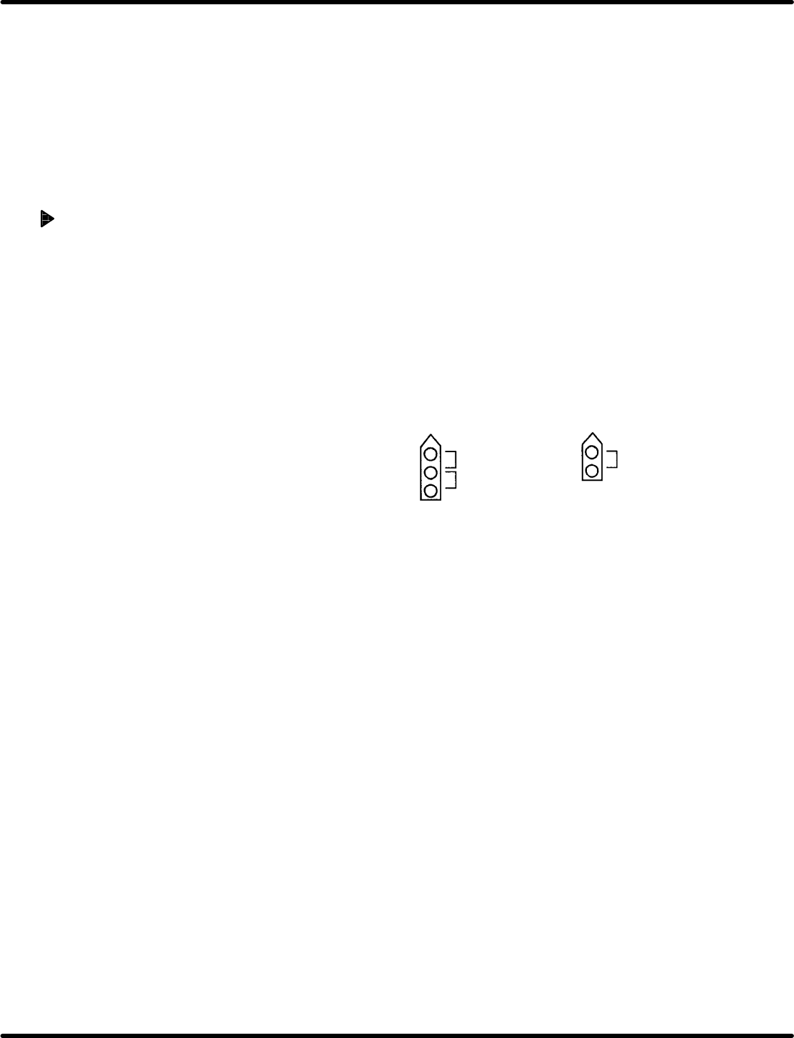
10. After soldering, cover pile up the coating
(two−liquid quick bonding) to cover the
distortion gauge and gauge terminal.
=CHECK=
x Apply coating, not to bulge it it out of the
chuck levers.
x Hold the lead wire and chuck levers in
place until coating is cured completely .
Distortion
gauge
No gap
Gauge terminal
Distortion
gauge
Gauge terminal
Lead wire
Coating state drawing
Gauge
5.16 Replacing Anvil Distortion Gauge
SERVICE MANUAL
RH5
5.16−5
DA3SEC−83−8YO−A0
11. Leave it until the coating does not stick to your
hand (3−4 hours) and assemble the chuck
levers A/B, shaft, fixed/movable blades, then
tighten them with each fitting.
=CHECK=
x Too ling fitting bolt of anvil movable blade
may affect the coating.
x Improper alignment of the anvil blades may
cause detection error .
Checking distortion gauge and
adjusting insertion detection
amplifier
1. After assembling the anvil unit, measure the
resistance with the connectors of spiral tube
and check for short−circuit.
=REFERENCE=
Resistance: 110−130:
=CHECK=
When measuring the resistance, do not
squeeze the terminal of the measurement
device into the connector forcibly.
Squeezing the terminal forcibly may let
the connector pins stay open and disable
to close.
2. Install the anvil unit into the machine and
connect the connectors of the spiral tube with
the amplifier to operate the trial insertion.
Then adjust the insertion detection amplifier.
=REFERENCE=
The procedure for adjusting the volume of the
insertion detection amplifier for RH5 series is
different from other series machines.
For RH5 series, the sensitivity increases by
turning the volume to left and decreases by
turning to right.
Measuring points for resistance
Check lever A Check lever B
Measure between
1 and 2
Measure between
2 and 3
Measure between
1 and 2