Q170226E01.pdf - 第303页
RH5 8.3 List of Jumper Switch Settings SERVICE MANUAL 8.3−6 DA3SEC−85−540−B0 CPU−286E (I)−12 No. 9981
8.3 List of Jumper Switch Settings
SERVICE MANUAL
RH5
8.3−5
DA3SEC−85−540−B0
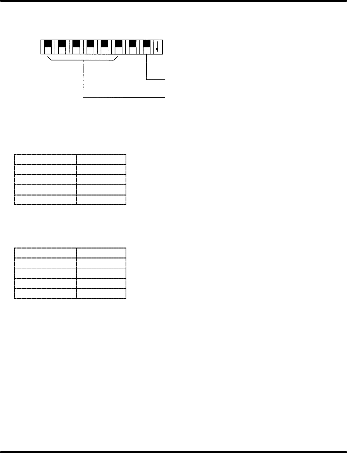
General−purpose input switch on the main side − JP9, 10
Permits leading from main PIO. ON: 0, OFF: 1
Not used
General−purpose
switch
1 23 45678
ON
Offset adjusting volume − VRB1 to 4
Enables adjustment of command output voltage offset.
Volume
Axis
VRB1 1st axis
VRB2 2nd axis
VRB3 3rd axis
VRB4 4th axis
Gain fine−adjusting volume − VRA1 to 4
Gain can be fine−adjusted around the setting voltage 1 (command output voltage).
Gain
Axis
VRA1 1st axis
VRA2 2nd axis
VRA3 3rd axis
VRA4 4th axis
RH5
8.3 List of Jumper Switch Settings
SERVICE MANUAL
8.3−6
DA3SEC−85−540−B0
CPU−286E (I)−12 No. 9981
8.3 List of Jumper Switch Settings
SERVICE MANUAL
RH5
8.3−7
DA3SEC−85−540−B0
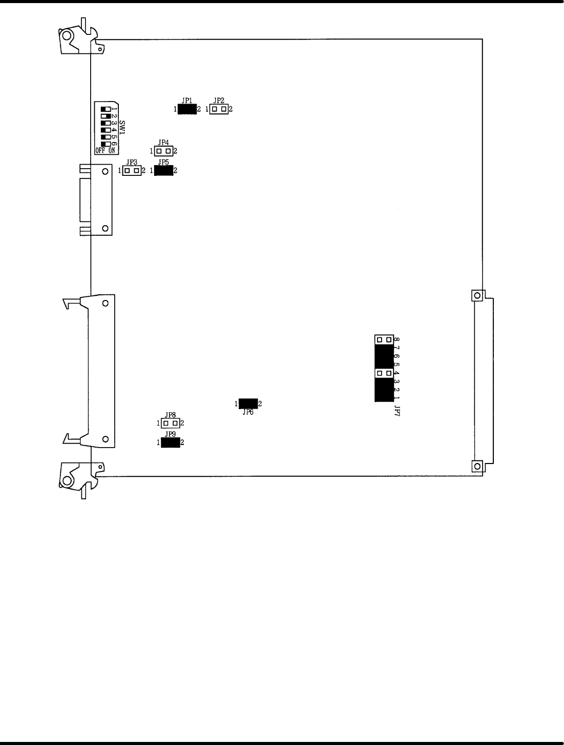
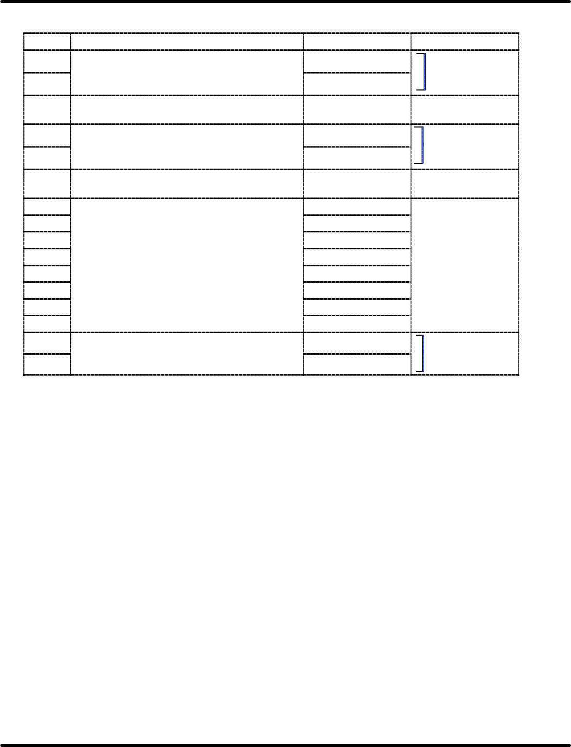
Jumper switch setting table
Name Description Short Open
JP1 Selects the type of CGROM installed by user. 512 *
Select
either
one
JP2 256
S
e
l
ect e
i
t
h
er one.
JP3 Selects the polarity of SYNC signal for CRT
display.
Positive logic *
JP4 Selects reversing color function in color display. Enabled
Select
either
one
JP5 Disabled *
Select
either
one
.
JP6 Selects whether or not to use SIO interrupt
mode.
Vector mode Non−vector mode
JP7−1 Selects the signal line for
it ti
P2
b
(PIC IRO)
INT0 signal *
JP7−2
interrupting P2 bus.
(
)
(PIC IR1)
INT1 signal *
JP7−3
(
)
(OUT0)
INT2 signal *
JP7−4
(OUT1)
INT3 signal *
Not
sed
JP7−5
(PIC IR4)
(PIC
IR5)
INT4 signal *
Not used
JP7−6
(PIC IR5)
(PIC
IR6)
INT5 signal *
JP7−7
(PIC IR6)
(PIC
IR7)
INT6 signal *
JP7−8
(PIC
IR7)
INT7 signal
JP8 Selects the CTS input signal source for
communication
CH
−
D
External CTS
Select either one.
JP9
communication
CH
−
D
.
Internal RTS *
Select
either
one
.
Items marked with an asterisk denote standard factory−setting shipment settings.