Q170226E01.pdf - 第276页
7.2 AC Servomotor Adjustment SERVICE MANUAL RH5 7.2−21 DA3SEC−84−300−A0 User Constant Cn−01 (Memory Switch) List Selected item Bit No. De− fault Description Command input Sequence signal input Refer− ence Control mode B/…

RH5
7.2 AC Servomotor Adjustment
SERVICE MANUAL
7.2−20
DA3SEC−84−300−A0
Selected
item
Bit No. De−
fault
Description Reference
Mode switch (Only
speed control)
D/C 0/0 <Torque command>
It can be activated when the set torque vale is conformed
to user constant Cn−0C.
0/1 <Speed command>
It can be activated when the set value is conformed to
user constant Cn−0C.
00
1/0 <Acceleration>
It can be activated when the set value is conformed to
user constant Cn−0E.
1/1 Mode switch function not supported
External brake E 0 No brake command function 0
1 Brake command function supported
Overload alarm F 0 No overload alarm function 0
1 Overload alarm function supported
=REFERENCE=
x Bit No. 8: Follow the same procedure as in bit No. 6 for abnormal stopping when controlling the
torque.
x Bit No.09: Selects 0 or 1 after completing zero speed stop is selected.
x Bit No. C/D: Selects the conditions for activating the mode switch.
When the mode switch activates, the speed control will be switched to P control. This
is, however, available only for controlling the speed.

7.2 AC Servomotor Adjustment
SERVICE MANUAL
RH5
7.2−21
DA3SEC−84−300−A0
User Constant Cn−01 (Memory Switch) List
Selected
item
Bit
No.
De−
fault
Description Command input Sequence
signal input
Refer−
ence
Control
mode
B/A 0/0 <Speed control>
x Controls the speed
normally.
x Regards ICN−24 (P−CON
)
as a changeover signal for
P/PI control.
Speed command (IN−A)
Auxiliary command input
(IN−B)
P−CON
OFF: PI control
ON: P control
0/0
0/1 <Speed control with zero
clamp function>
x Stops the motor with zero
speed aside from the
speed command.
x Regards ICN−24 (P−CON
)
as a zero clamp ON/OFF
signal.
P−CON
OFF: Zero
clamp OFF
ON: Zero
clamp ON
1/0 <Torque control 1>
x Controls output torque from
the motor via torque
command (IN−A).
x IN−B cannot be used.
Torque command
(IN−A)
None
1/1 <Torque control 2>
x Use ICN−24 (P−CON
)
as the switching
signal−selectable
between torque control
and speed control.
In torque controlling:
x Controls output torque from
the motor via torque
command (IN−B).
x Speed limit can be
controlled with remote
control. (IN−A)
Speed can be controlled in
both CCW and CW
directions via IN−A voltage
(+).
In torque control:
Torque command (IN−B)
Speed limit (IN−A)
In speed control:
Speed command (IN−A)
=REFERENCE=
x Outside the limit
speed range, the
torque proportional to
the difference with the
limit speed is fed back
negatively to take
back the speed to
within the limit range.
Therefore, the motor
speed limit value
varies according to
the load condition.
x Contact us the motor
speed decreases
continuously by
torque command
P−CON
OFF: Torque
control
ON: Speed
control
RH5
7.2 AC Servomotor Adjustment
SERVICE MANUAL
7.2−22
DA3SEC−84−300−A0
Selected
item
Bit
No.
De−
fault
Description Command input Sequence
signal input
Refer−
ence
Control
mode
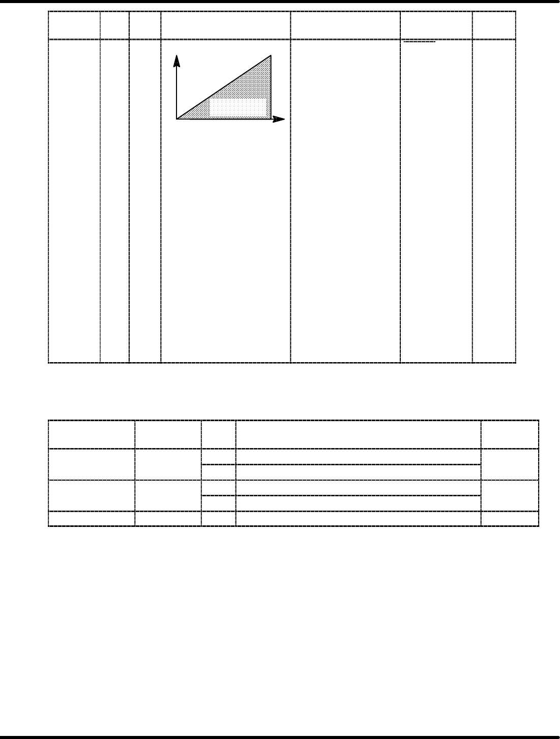
B/A 1/1
Motor speed
IN−A
Speed control
range
In torque control:
Torque command (IN−B)
Speed limit (IN−A)
In speed control:
Speed command (IN−A)
=REFERENCE=
x Outside the limit
speed range, the
torque proportional to
the difference with the
limit speed is fed back
negatively to take
P−CON
OFF: Torque
control
ON: Speed
control
0/0
When controlling speed:
x Input speed command
from IN−A.
x IN−B cannot be used.
gy
back the speed to
within the limit range.
Therefore, the motor
speed limit value
varies according to
the load condition.
x Contact us the motor
speed decreases
continuously by
torque command
=REFERENCE=
Cn−02: Reserved
User Constant Cn−02 (Memory Switch) List
Selected
item
Bit No. De−
fault
Description Reference
Reverse turn mode 0 0 Set the normal turn in CCW direction. 0
1 Set the normal turn in CW direction.
Encoder error 1
SR
BY
l
0 Detects encoder trouble. 0
SR BY only
1 Does not detect encoder trouble.
Reserved 2−F Do not set.