Q170226E01.pdf - 第371页
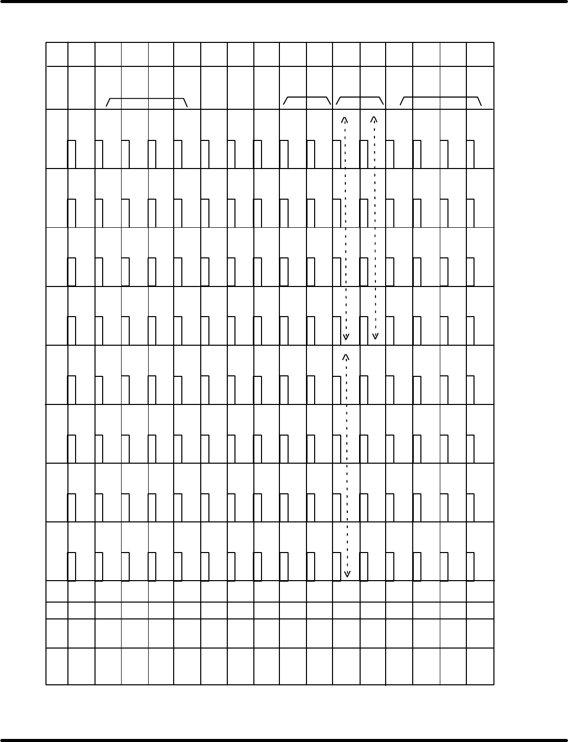
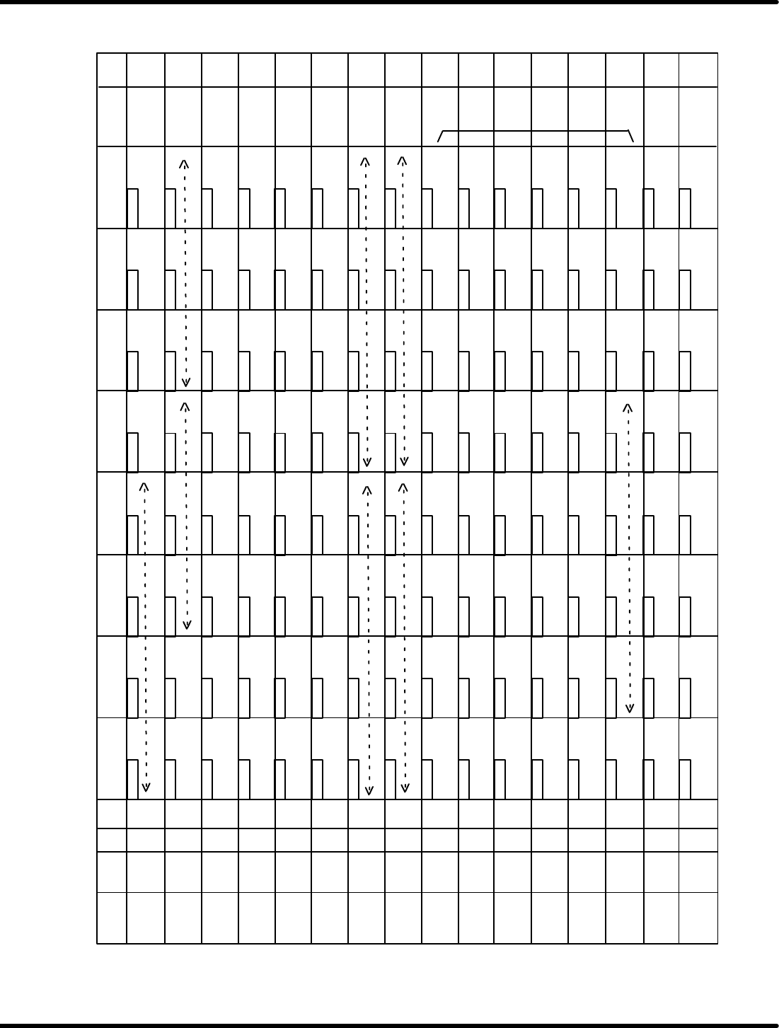
RH5 8.8 Monitoring I/O Signals SERVICE MANUAL 8.8−10 DA3SEC−85−520−A0 ADDRESS LABEL BLK DEV 7b i t 6b i t 5b i t 4b i t 3b i t 2b i t 1 bit 0 bit COMMENT 7010 0 7010 1 7010 2 7010 3 7010 4 7010 5 7010 6 7010 7 7010 8 701…
8.8 Monitoring I/O Signals
SERVICE MANUAL
RH5
8.8−9
DA3SEC−85−520−A0
ADDRESS LABEL
BLK DEV
7bit 6bit 5bit 4bit 3bit 2bit
1 bit 0 bit COMMENT
700D 0
700D 1
700D 2
700D 3
700D 4
700D 5
700D 6
700D 7
700D 8
700D 9
700D A
700D B
700D C
700D D
700D E
700D F
3 200
207
217
227 **2
247
257
267
277
307 T39
317 T47
327 ZD7
337 ZD15
347 T7
357 T15
367 T23
377 T31
216
226 **2
246
256
266
276
306 T38
316 T46
326 ZD6
336 ZD14
346 T6
356 T14
366 T22
376 T30
205
215
225 **2
245
255
265
275
305 T37
315 T45
325 ZD5
335 ZD13
345 T5
355 T13
365 T21
375 T29
206 200
371 T25
361 T17
351 T9
341 T1
331 ZD9
31 1 T41
321 ZD1
251
261
271
301 T33
201
211
221 **2
231 **2
241 **2
210
220 **2
250
260
230 **2
240
270
310 T40
320 ZD0
300 T32
340 T0
350 T8
330 ZD8
370 T24
360 T16
203
213
223 **2
233 **2
243 **2
253
263
273
303 T35
313 T43
323 ZD3
333 ZD11
343 T3
353 T1 1
363 T19
373 T27
362 T18
202
212
222 **2
232 **2
242 **2
252
262
272
302 T34
312 T42
322 ZD2
332 ZD10
342 T2
352 T10
372 T26
204
214
224 **2
234 **2
244 **3
254
264
274
304 T36
314 T44
324 ZD4
334 ZD12
344 T4
354 T12
364 T20
374 T28
3 200
Loader belt motor
(reverse)
Guide chuck
open/close
Parts feeder
Origin flag
CNC−ZR
(Head rotation)
M311
(7−227)
ZLR2
(7−237)
(7−167)
PCB exists at
insertion position
(7−177)
Unloader
(7−207)
Accommodation
vibration
Before interruption
Cutter 2
(Insert)
Error flag
CNC−RZ
M201
(7−236)
Solenoid/mecha
valve changeover
Insertion pusher
down lock
(Loading)
Completion flag
CNC−ZR
M111
(7−225)
PC board stopper
(7−235)
Completion flag
PC wait stock 1
(7−205)
Invert error
Guide pin
intermediate lock
Invert chuck
up/down
Origin flag
CNC−ZL
PC board
positioning
Inching
(7−234)
(7−224)
Loader belt motor
reverse
HOLD Z
(7−174)
Positioning (2)
(7−204)
Invert error
(7−164)
Cutter forward
(7−214)
Loader normal turn OFF
Insertion chuck up
lock
Invert chuck
swivel
PC board stopper
OFF memory
Arm swing
Invert chuck open/
close
Feed select
Cam interlock chuck
open/close
Error flag
CNC−ZL
M100
PC board push−in
ZLR2
(7−233)
Thermal ON monitor
ZLR2
(7−173)
Loader
(7−163)
Component detect
PC board supply
(7−222)
Width adjust axis
unloader
(7−161)
Width adjust step −
Edge positioning
Standard feed flag
Error flag
(7−221)
Width adjust axis
X−Y
(7−231)
Vacuum timer 1
Origin flag
(7−171)
Arm reverse timer
(7−201)
Positioning (1)
Transfer chuck
open/close
Rail down
PC board
positioning
High speed feed
flag
(7−220)
Width adjust axis
loader
ZL
(7−160)
Width adjust step +
(7−170)
PC board at recognition
position
(7−200)
Transfer chuck close H
3 200
3 200
3 200
3 200
3 200
3 200
3 300
3 300
3 300
3 300
3 300
3 300
3 300
3 300
M311
(7−217)
Signal tower OFF
Insertion chuck
open/close
Unloader belt
motor
M201
(7−226)
ZLR1
(7−166)
Invert
(7−176)
P wait stock 2
(7−206)
Loading ready error
(7−216)
signal tower ON
Cutter 1
Loader belt motor
(normal turn)
M111
ZR
End terminal detection
check memory
(7−175)
(7−215)
Unloader exit PC
board
M101
M101
ZL
Transfer cylinder
M100
(7−223)
Width adjust axis
reference pin
(7−203)
Recognition start
(7−213)
Loader
(7−172)
Loader
(7−202)
Recognition start
(7−212)
Feed monitor
(7−162)
ZLR1
Insertion pusher up
lock
Completion flag
CNC−ZL
M21
M21
(7−232)
Vacuum timer 2
M11
M11
M1
M1
(7−211)
Loader (edge
positioning)
PC board stopper
ON memory
Head Y direction
lock
(7−230)
Unloader belt motor stop
ZL
(7−210)
Transfer chuck close L
XXXX: Contact No. of timer
Dummy Table−4 RH5
M command
(Component BLK)
M command
(Component BLK)
For timer
dummy
area 2
For timer
dummy
area
For X axis
2−division
Temporary
memory
dummy
area
ZR
Component invert
insertion
ZLR1
After interruption
Pitch allocation
PC board punch
OFF memory
PC board punch
ON memory
Operation
panel key
input
dummy
area
PC board punch OFF
PC board punch ON
(7−165)
Invert
237 **2
236 **2 235 **2
ZR
RH5
8.8 Monitoring I/O Signals
SERVICE MANUAL
8.8−10
DA3SEC−85−520−A0
ADDRESS LABEL
BLK DEV
7bit 6bit 5bit 4bit 3bit 2bit
1 bit 0 bit COMMENT
7010 0
7010 1
7010 2
7010 3
7010 4
7010 5
7010 6
7010 7
7010 8
7010 9
7010 A
7010 B
7010 C
7010 D
7010 E
7010 F
40
40
40
40
40
40
40
40
4 100
7
17
27
37
47
57
67
77
107 (High)
117
127
137
147
157
167
177
16
26
36
46
56
66
76
106
126 **2
146
156
166
176 **6
5
15
25
35
45
55
65
75
105
1 15 **2
125 **2
135 **2
145
155
165
175 **7
6 0 **1
171
161
151
141 **2
131 **2
111 **2
121 **2
51
61
71
101
1 **1
11
21
31
41
10
20
50
60
30
40
70
1 10 **2
120 **2
100
140 **2
150
130 **2
170
160
3
13
23
33
43
53
63
73
103
1 13 **2
123 **2
133 **2
143 **2
153
163
173
162
2
12
22
32
42
52
62
72
102
1 12 **2
122 **2
132 **2
142 **2
152
172
4
14
24
34
44
54
64
74
104
1 14 **2
124 **2
134 **2
144 **3
154
164
174 EU safety
4 100
4 100
4 100
4 100
4 100
4 100
4 100
Online
Full auto Semiauto
Operation mode
Command ON flag
Head in turn
(C5UP)
PC board supply stop
Insert start
Recognition
complete
Reference pin −
Reference pin −
(Super high speed
enable)
7.5 All
Guide chuck close
Parts feeder
Loader belt motor
(reverse)
(Head rotation)
RHU/RHX flag
(For debugging)
Recognition complete
During inserting
(C5UP)
PC board take−out
inhibited
Z axis in operation
**5
**8
Edge /pin
positioning
Width adjust step
Unloader −
Unloader −
Unloader +
Unloader +
Loader +
Loader +
(High)
Insertion chuck
close
(High)
(High)
(High) (High) (High) (High)
(High)
(High)
OP−START
2
CNC−X origin
CNC−X complete
CNC−X error
High speed
Head Y direction
lock
Transfer chuck
open
Rail down
PC board
positioning
(Recognition
camera)
PC board
supply stop
OP−RESET
Parts exhaust count
48
1
2
4
Manual
STOP MODE
1block
(Auto, semi)
Loader ON
Brake releasing
RH/RHUX flag
EOP command
Invert unit
Yes / No
XY table −
XY table −
(5.0 all/10)
5.0/10 all
Insertion pusher
down lock
(Feed lock release)
Cutter 1
Loader belt motor
(normal turn)
(Loading)
(Insert)
Reference pin
Unloader
XY table
7.5 or 10/5.0 or 7.5
(Width adjust (mode)
Recognition start
(each point)
(Width adjust)
Auto/manu
Recognition start
(as a package)
Loader
Head speed
Servo lock release
lamp
PMC − camera
origin
PMC − camera
complete
PMC − camera
error
Loader −
Loader −
Reference pin +
Reference pin +
(5.0)
5.0
Guide pin
intermediate lock
Invert chuck down
PCB stopper/PC
board positioning
Inching
Width adjust with no
regard to PC board
High speed/standard
machine
Replacement (left)
Replacement
(right)
2−division/
connection flag
CNC − cam
complete
CNC − cam error
(2.5/7.5 all)
2.5/10
Insertion chuck up
lock
Invert chuck swivel
Transfer cylinder
PC board push−in
PCB flow
Reverse/normal
CNC−ZL origin
CNC−ZL complete
CNC−ZL error
Width adjust step
(Low/
Super high speed 2)
Low speed
Insertion pusher
up lock
Invert chuck close
Feed select
Safety input reset
CNC−Y origin
CNC−Y complete
CNC−Y error
XY table +
XY table +
(Middle/
Super high speed 1)
Middle speed
Cam interlock chuck
open/close
Arm swing
Edge positioning
(Camera origin
return)
Key entry via
sub−control
panel
Link Table−1 RH5
PH error
enable/disable
Start key other
than safety input
Single feed/
double feed
Recognition yes flag
Continues width adjusting
Continues width adjusting
(7.5)
7.5
Component
inverting
(Cutter)
Cutter 2 (High)
PC board punch
out/PC board supply
PC board punch
out unit exists
New self−width
(Disclosure)
PC board punch
out
**1: Main set, SEQ reset **2: Toggle SW **3: One shot SW **4: Main set (***): Unprocessed
**5: It is ON in JOG operation, teaching, moving **6: MEND of each point will be returned when the cam is rotated at single PC recognition.
**7: MEND will be returned when the cam is not rotated at single recognition. **8: It is set when the command ON at NC data end.
SEQ m MAIN
116 **2
Unloader belt
motor
136 **2
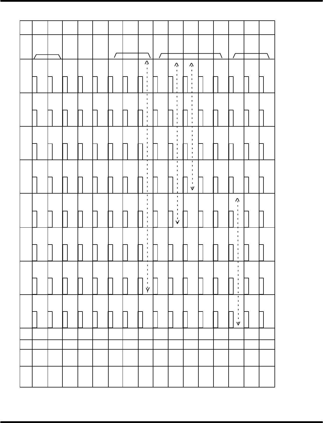
8.8 Monitoring I/O Signals
SERVICE MANUAL
RH5
8.8−11
DA3SEC−85−520−A0
ADDRESS LABEL
BLK DEV
7bit 6bit 5bit 4bit 3bit 2bit
1 bit 0 bit COMMENT
7011 0
7011 1
7011 2
7011 3
7011 4
7011 5
7011 6
7011 7
7011 8
7011 9
7011 A
7011 B
7011 C
7011 D
7011 E
7011 F
Signal tower
factor
207
217
227 Niigata
237
247
257
267
277
307
317
327
337
347
357 D22
367 D7
377
216
226
236
246
256
266
276
306
316
326
336
346
356 D21
366 D6
376 D14
205
215
225
235
245
255
265
275
305
315
325
335
345
355 D20
365 D5
375 D13
206
200
371 D9
361 D1
351 D16
341 D24
331
31 1
321
251
261
271
301
201
211
221
231
241
210
220
250
260
230
240
270
310
320
300
340 D23
350 D15
330
370 D8
360 D0
203
213
223
233
243
253
263 R side
273
303
313
323
333
343
353 D18
363 D3
373 D11
362 D2
202
212
222
232
242
252
262 L side
272
302
312
322
332
342 D25
352 D17
372 D10
204
214
224
234
244
254
264
274
304
314
324
334
344
354 D19
364 D4
374 D12
Link Table−2 RH5
4 200
4 200
4 200
4 200
4 200
4 200
4 200
4 200
4 300
4 300
4 300
4 300
4 300
4 300
4 300
4 300
Blue flashing
X/Y/Z axis
malfunction input
CNC−ZR origin
CNC−ZR complete
CNC−ZR error
Blue lit
Rear console
enable signal
During automatic
operation
Auto recovery
marking
Loader ON during
pass through
SC run check
1−>0
During inverting
Invert error flag
Internal flag during
head rotating
Invert swivel
memory
Reference pin
Feed start
timing
Signal tower
ON/OFF
Camera move
ready
insert MEND
condition
Unloader
Width adjust ready
PC board check
timing
Recognition complete at
each point
Recognition complete
internal flag
Invert error flag
(insert)
Guide pin
recognition stop
6bit
Auto recovery
stock
In operation
Red lit
During error
stop
Optical loop
error check start
Image signal
changeover (0: CPU,
1: RCG)
5bit
Safety input
memory
Recognition status
check memory
Z complete
(For MEND)
XY table
Head ready
(SEMI)
Invert MEND
condition
Head ready
(AUTO)
Feed complete
Loader
Red flashing
Yellow flashing
Yellow lit
M/LL
Backlight lit
(0: ON, 1: OFF)
Buzzer
Parts exhaust cassette display data bit
4bit
2bit 1bit
0bit
Signal tower
blue factor
1
1
2
23
4
4
5
Insertion check
end command
Transfer chuck
close timing
Unloader exit
PC board
Forced oiling
Signal tower
blue dummy
Edge positioning
OFF memory
Condition error
(invert) 1
Data shift timing
Camera
interlock
MEND memory
(SEMI)
Dummy
area 2
For Z
axis
2−division
Camera
interlock 2
Edge positioning
ON memory
Condition error
(invert) 2
Invert unit original
position
EOP condition
MEND memory
(AUTO1)
MEND memory
(AUTO2)
Recognition
MEND condition
Width adjust
ready
P WAIT STOCK
Cut waste drop
timing
Invert position
Insertion detection OK memory
Cutter 1 output
dummy
Standby position
moveSWLEDON
Parts replacement
SW LED ON (L side)
Parts replacement
SWLEDON(Rside)
Recognition light
source (Recognition
teaching screen)
Standby position
moveSWLEDON
Cutter 2 output
dummy
Transfer chuck
open command
Semiauto
MEND condition
Temporary
memory
dummy
area
R side set bit
Lsidesetbit
Internal flag during
head rotation stop
Pioneer
Electric
Unishia
During transfer error
stop
Aisin AW
During parts exhaust
stop
Unisia
During insertion error
stop
Arukatel
Transfer signal
Aishin
In spare cassettes
production
Reacceleration
info. at halfway
Trial flag
(not used)
RH5 cam
shaft for
control
Z axis R being
used
Z axis L being
used
3bit
Insertion stored
3
PC board punch out
command memory
PC board
punching
Cam shaft
operating
SEQ m MAIN