Q170226E01.pdf - 第298页
8.3 List of Jumper Switch Settings SERVICE MANUAL RH5 8.3−1 DA3SEC−85−540−B0 8.3 List of Jumper Switch Settings DA3SEC−85−540−B0 Sentence No. 8.3.1 CNC−4S (I) Board Setting CNC−4S (I) TP4 4−axis voltage terminal TP3 3−ax…

RH5
8.2 List of Software Settings
SERVICE MANUAL
8.2−8
DA3SEC−85−470−B0
= MEMO =
8.3 List of Jumper Switch Settings
SERVICE MANUAL
RH5
8.3−1
DA3SEC−85−540−B0
8.3 List of Jumper Switch Settings
DA3SEC−85−540−B0
Sentence No.
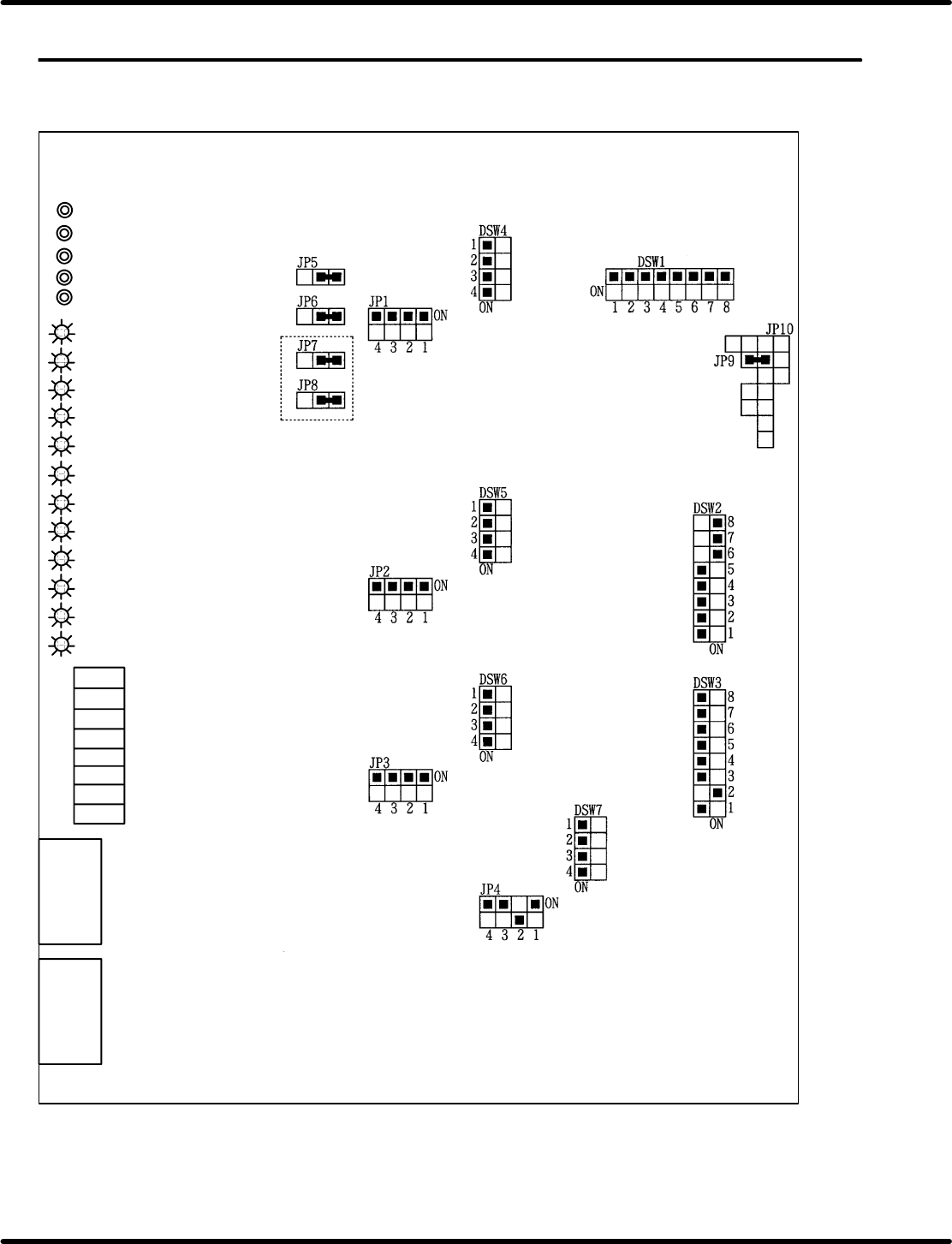
8.3.1 CNC−4S (I) Board Setting
CNC−4S (I)
TP4 4−axis voltage terminal
TP3 3−axis voltage terminal
TP2 2−axis voltage terminal
TP1 1−axis voltage terminal
TPG Ground terminal
LED 12 4−axis origin
LED 11 3−axis origin
LED 10 2−axis origin
LED 9 1−axis origin
LED 8 4−axis in operating
LED 7 3−axis in operating
LED 6 2−axis in operating
LED 5 1−axis in operating
LED 4 Master general purpose LED
LED 3 Master general purpose LED
LED 2 Master general purpose LED
LED 1 Master general purpose LED
VRB4
VRB3
VRB2
VRA1
VRA2
VRA3
VRA4
VRB1
4−axis offset
3−axis offset
2−axis offset
1−axis offset
4−axis gain
3−axis gain
2−axis gain
1−axis gain
CN2
CN1
RH5
8.3 List of Jumper Switch Settings
SERVICE MANUAL
8.3−2
DA3SEC−85−540−B0
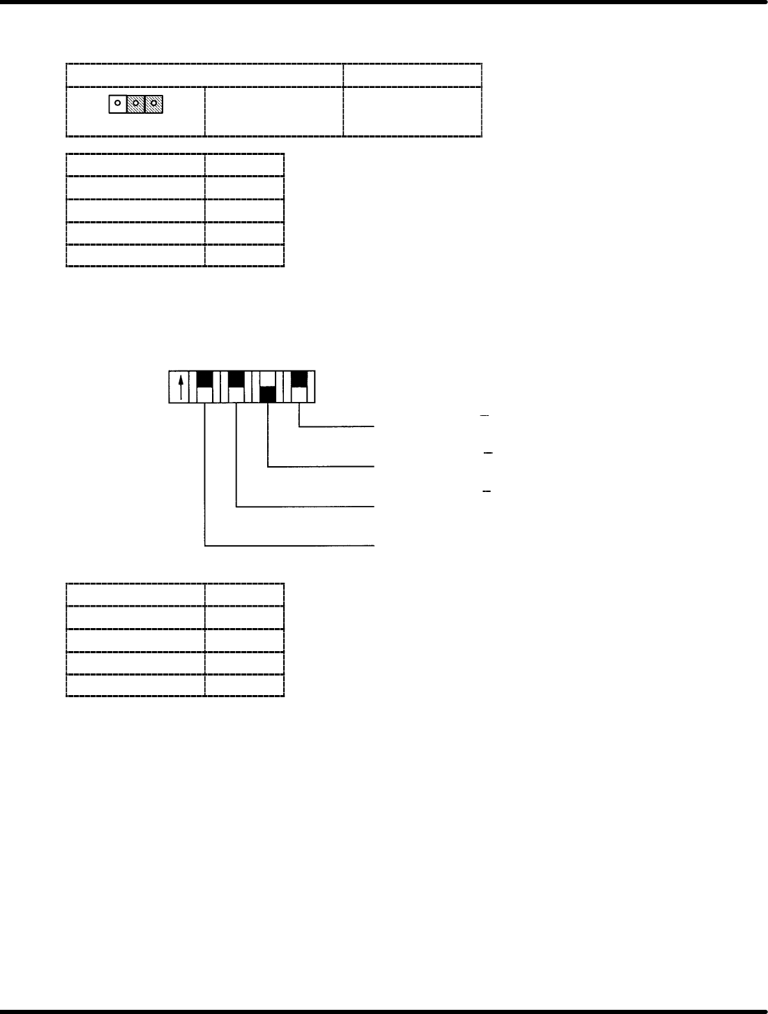
Command voltage full scale changeover jumper post − JP5 to 8
Set the output voltage at r10V.
Short circuit condition
Output
123
2−3 shot r10V
Jumper switch Axis
JP5 1st axis
JP6 2nd axis
JP7 3rd axis
JP8 4th axis
Encoder input logic select switch − JP1 to 4
Allows encoder input logic of phases A, B and Z to be selected.
Phase A
Phase B
Phase Z
General−purpose
input switch
OFF: A
ON: A
OFF: B
ON: B
OFF: Z
ON: Z
ON
OFF
JP4321
Jumper switch Axis
JP1 1st axis
JP2 2nd axis
JP3 3rd axis
JP4 4th axis