Q170226E01.pdf - 第246页
SERVICE MANUAL RH5 7.0−1 7 ダミー (Section のレベル 1) 7.0 ダミー (Section のレベル 2)
6.1 Checking Maintenance Precision
SERVICE MANUAL
RH5
6.1−8
DA3SEC−89−010−A0
No.
Check item
Description
Illustration
Criteria
Measured
value
35
36
37
38
39
OK/NG
Visual check
*******
0to0.03mm
mm
0to0.03mm
mm
46.7 to 49.3 kPa
kPa
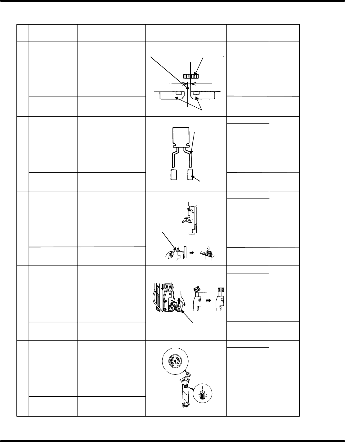
Transfer chuck
and cutter center
Check the cutter closing
center at the origin with the
transfer chuck closing
center as the reference.
Cutter push depth: 0.1 mm
Center position
must be matched
Transfer chuck
claw
Cutter
Insertion chuck
height precision
Bolt
M6 x 6 OK/NG
White marker
check
OK/NG
White marker
check
OK/NG
White marker
check
OK/NG
White marker
check
Thickness gauge
Bolt M5 x 2
Bolt
M5 x 2
Bolt Pressure valve
Head stopper
setting
Rotate the camshaft to the
0position and check that
the insertion head and the
stopper touch completely
without any clearance.
Bolt
M6 x 4
Electronic
component lead
Guide pin
OK/NG
White marker
check
OK/NG
Visual check
*******
*******
Rack stopper
setting
Vacuum pump
Set the vacuum pressure
by regulating the pressure
valve of the vacuum pump.
Ensure that the stopper
touches entirely in the 90
position without clearance.
Check if there is no play in
the insertion chuck.
No clearance here
No play in the
rotating direction
Using the electronic
components whose precision
have been checked by the
taping gauge, check that the
center of the lead of the
electronic component and
that of the guide pin are
matched.
*******

SERVICE MANUAL
RH5
7.0−1
7ダミー(Sectionのレベル1)
7.0ダミー(Sectionのレベル2)

RH5
SERVICE MANUAL
7.0−2
DA3SEC−84−000−A0
DA3SEC−84−000−A0
Sentence No.
7. MAINTENANCE GUIDE
(CONTROL)
This chapter describes the adjustment procedures related to controls such as AC
servomotor drivers.
x Consider and practice safety at all times when operating or servicing the
equipment.
x Be sure to read “Safety Precautions” in chapter 1 carefully.