Q170226E01.pdf - 第111页
RH5 5.2 X−Y T able Motor Replacement SERVICE MANUAL 5.2−2 DA3SEC−83−8JO−A0 7. T ighten the N coupling nut on the motor side temporarily . =REFERENCE= x Follow steps 1 through 7 to replace the Y−axis motor . x Be sure to …
Flat head
machine
screw
Motor side nut
(17 mm )
N coupling
Ball screw
Ball screw side nut
(17 mm )
Bracket
Motor shaft
Bolt B
Motor
5.2 X−Y Table Motor Replacement
SERVICE MANUAL
RH5
5.2−1
DA3SEC−83−8JO−A0
5.2 X−Y Table Motor Replacement
DA3SEC−83−8JO−A0
Sentence No.
Required tools
x Allen wrench
Ball
screw
Bracket
Cover
Motor
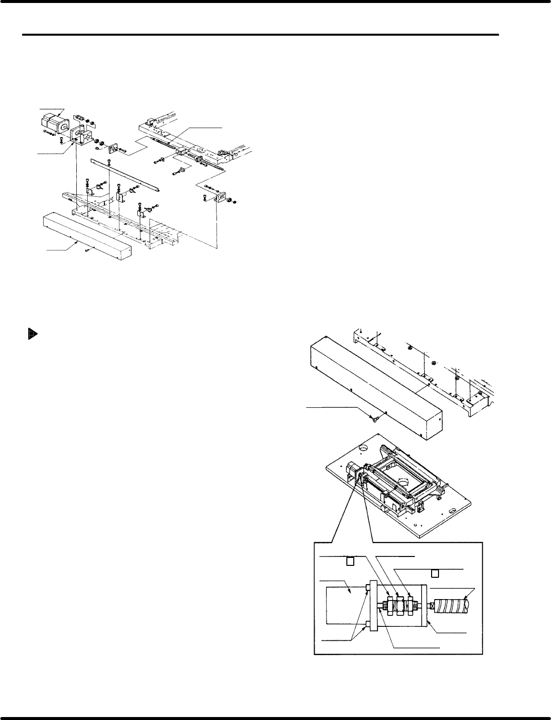
Motor removal and mounting (X−axis)
1. Change the CH4 (speed loop gain) of the X
axis (Y axis) driver from 200 to 80 before
turning OFF the power to the machine. (Refer
to ‘7.3 Digital Operator’ for details on how to
change the value.)
2. Turn OFF the power and disconnect the motor
connectors.
3. Remove the ball screw cover of the X axis (Y
axis).
4. Loosen the N coupling nut on the motor side.
5. Remove bolts B (x 4) and the motor.
=REFERENCE=
x When removing bolts B, support the
motor by hand so that it doesn’t drop out
of position.
x Strip away all old sealant tape from the
threaded part of the N coupling and
rewrap with new tape.
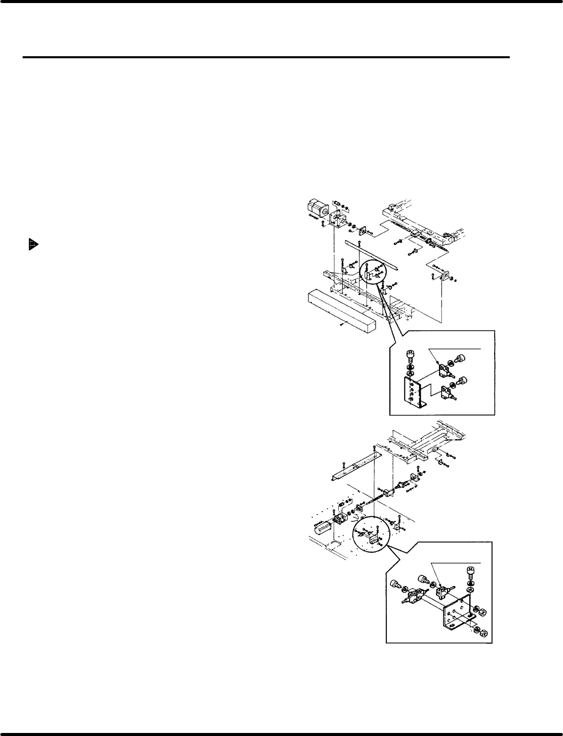
6. Mount the new motor and fix with bolts B (x 4).
=CHECK=
Ensure that the motor axis inserts smoothly
into the N coupling.

RH5
5.2 X−Y Table Motor Replacement
SERVICE MANUAL
5.2−2
DA3SEC−83−8JO−A0
7. Tighten the N coupling nut on the motor side
temporarily.
=REFERENCE=
x Follow steps 1 through 7 to replace the
Y−axis motor.
x Be sure to proceed to ‘5.3 X−Y Table
Origin and Over Limit Check and
Adjustment’ after replacing the motor.
5.3 X−Y Table Origin and Over Limit Check and Adjustment
SERVICE MANUAL
RH5
5.3−1
DA3SEC−83−8KO−A0
5.3 X−Y Table Origin and Over Limit Check and
Adjustment
DA3SEC−83−8KO−A0
Sentence No.
When to perform
x After replacing the motor
x After repairing or replacing the X−Y table
x When insertion errors occur often
Required tools
x Allen wrench
x Box wrench
Checking origin position
1. Change the CH4 (speed loop gain) of the X axis
(Y axis) driver from 80 to 200.
2. Turn OFF the power to the machine once and
turn it back ON.
3. Set the origin board to the X−Y table.
=CHECK=
x Attach the reference pin (I4.0) to the
positioning lever.
x Make sure that the guide pin is not bent.
4. Create the following NC data.
N1 G1 M0 T0 V4 X0 Y0 Z0
N200400 0 0
N3 0 1 1 0 140.0 67.5 1
5. Input program offset as follows:
M: X=−160.00 Y=−255.00
LL: X=−250.00 Y=−385.00
6. Return the X−Y table to its origin manually.
X−axis origin
detection photonimic
Y−axis origin
detection photonimic