Q170226E01.pdf - 第140页
5.13 Insertion Head Insertion Chuck Height Check and Adjustment SERVICE MANUAL RH5 5.13−1 DA3SEC−83−8VO−A0 5.13 Insertion Head Insertion Chuck Height Check and Adjustment DA3SEC−83−8VO−A0 Sentence No. When to perform x W…

RH5
5.12 Insertion Head Chuck Opening/Closing Timing Check/Adjustment
SERVICE MANUAL
5.12−4
DA3SEC−83−8UO−A0
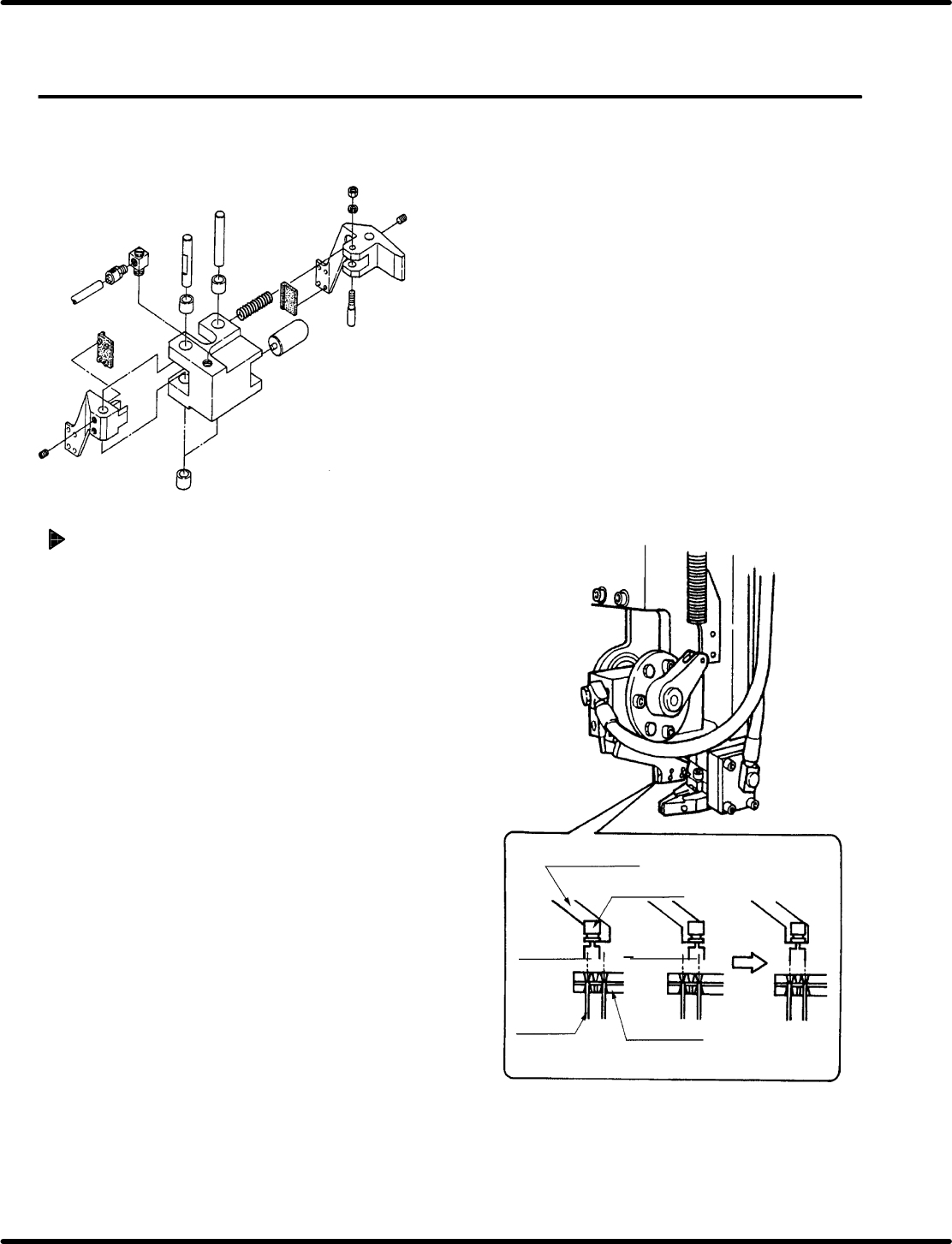
Insertion pusher timing adjustment
1. If the pusher high pressure does not turn ON,
reset timing so that SC22 turns ON at 280q and
OFF at 312q.
=CHECK=
x Before resetting the digital sequence
timer, set the mode to MANUAL 1 BLOCK
without fail.
x Select EDIT before changing angles.
x SC22 is the pusher high pressure timing
at low speed only.
The high pressure timing depends on the
speed as follows:
Medium speed (0.45 sec):
SC30, ON: 270 q, OFF: 312q
High speed (0.36 sec):
SC31, ON: 265 q, OFF: 312q
5.13 Insertion Head Insertion Chuck Height Check and Adjustment
SERVICE MANUAL
RH5
5.13−1
DA3SEC−83−8VO−A0
5.13 Insertion Head Insertion Chuck Height Check and
Adjustment
DA3SEC−83−8VO−A0
Sentence No.
When to perform
x When parts leads do not readily slip
into the guide chuck.
x When insertion errors occur
frequently.
x Allen wrench
x Gap gauge
Required tools
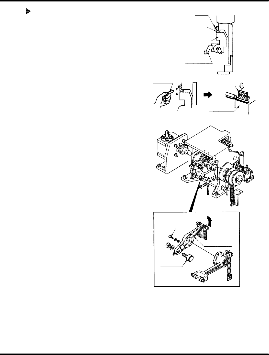
Insertion chuck height check
1. Turn ON the CAM ROTATION ENABLE and
INCHING switches on the sub−control panel in
the SEMIAUTO mode. Perform feeding and
cutting to make sure parts are chucked properly
to the transfer chuck.
2. After making checks, turn the RESET and
BRAKE RELEASE switches ON, rotate the hand
wheel until the digital sequence timer is at
approximately 195q position, and check handover
again.
Insertion chuck
Electronic
component
Underfeed
Overfeed
Guide pin
Guide chuck
(NG) (OK)
RH5
5.13 Insertion Head Insertion Chuck Height Check and Adjustment
SERVICE MANUAL
5.13−2
DA3SEC−83−8VO−A0
Adjusting insertion chuck height
(When underfeed occurs)
1. Loosen bolt A (x 2) until there is play in
the insertion head upper end stopper.
2. Turn the hand wheel until the cam shaft is
at the 0 q position on the digital sequence
timer, insert a gap gauge the same size
as the discrepancy when the insertion
chuck is in the chucking position,
between the upper stopper and the
insertion head. Without removing the
gauge, tighten bolts A (x 2) until fixing the
stopper in place.
=CHECK=
Fix the upper stopper such that the gap
gauge is flush against both the upper
end stopper and insertion head.
3. Remove the gap gauge and turn the hand
wheel until the cam shaft is at the 90q
position on the digital sequence timer.
4. Loosen bolts B (x 5) from the rear side of
the machine until there is some play in
the insertion head vertical lever.
Bolt A
Upper end stopper
Insertion chuck
Insertion head
Gap gauge
Upper end stopper
Insertion head
Bolt A
Head vertical lever
Cam follower