Q170226E01.pdf - 第155页
RH5 5.16 Replacing Anvil Distortion Gauge SERVICE MANUAL 5.16−6 DA3SEC−83−8YO−A0 = MEMO =
5.16 Replacing Anvil Distortion Gauge
SERVICE MANUAL
RH5
5.16−5
DA3SEC−83−8YO−A0
11. Leave it until the coating does not stick to your
hand (3−4 hours) and assemble the chuck
levers A/B, shaft, fixed/movable blades, then
tighten them with each fitting.
=CHECK=
x Too ling fitting bolt of anvil movable blade
may affect the coating.
x Improper alignment of the anvil blades may
cause detection error .
Checking distortion gauge and
adjusting insertion detection
amplifier
1. After assembling the anvil unit, measure the
resistance with the connectors of spiral tube
and check for short−circuit.
=REFERENCE=
Resistance: 110−130:
=CHECK=
When measuring the resistance, do not
squeeze the terminal of the measurement
device into the connector forcibly.
Squeezing the terminal forcibly may let
the connector pins stay open and disable
to close.
2. Install the anvil unit into the machine and
connect the connectors of the spiral tube with
the amplifier to operate the trial insertion.
Then adjust the insertion detection amplifier.
=REFERENCE=
The procedure for adjusting the volume of the
insertion detection amplifier for RH5 series is
different from other series machines.
For RH5 series, the sensitivity increases by
turning the volume to left and decreases by
turning to right.
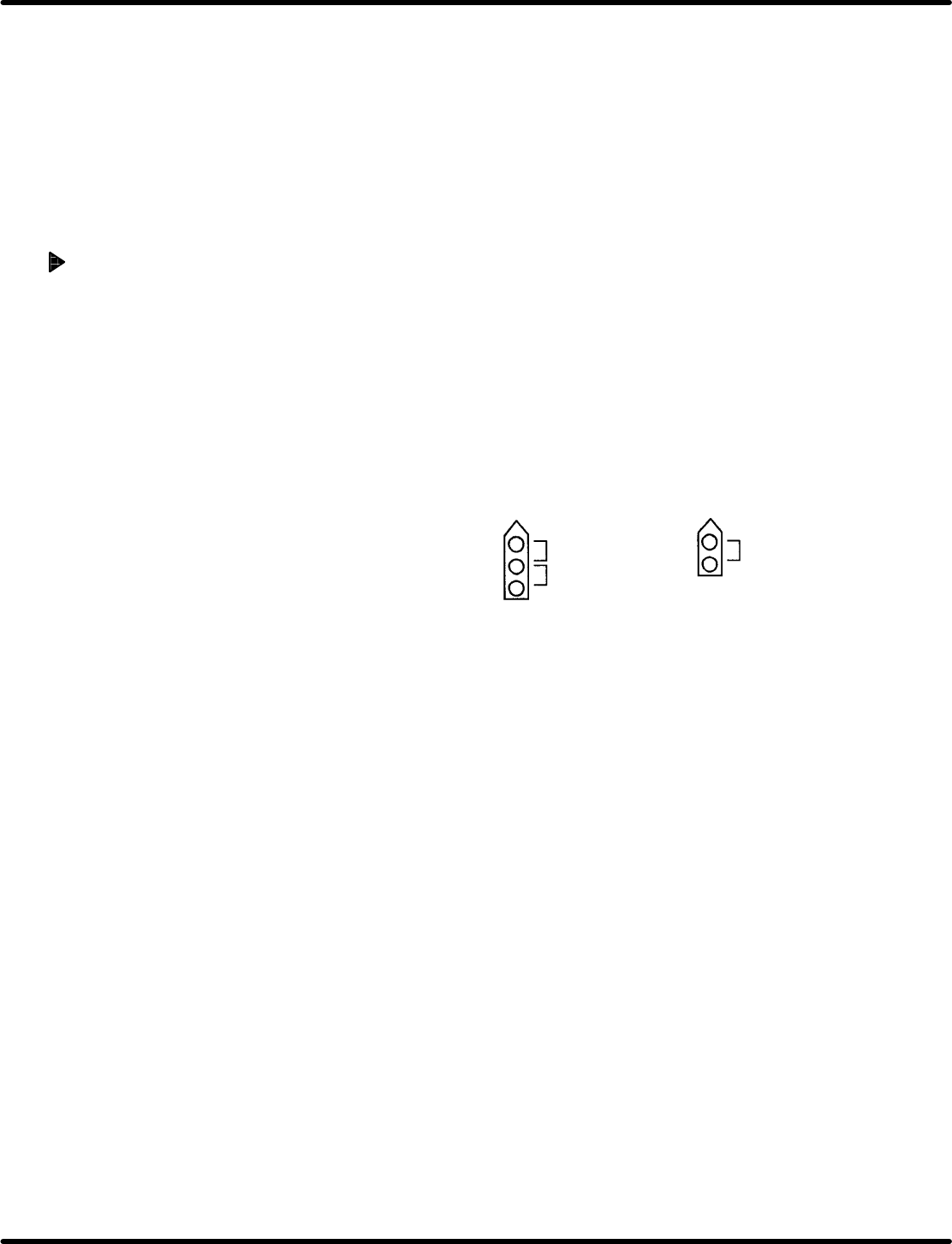
Measuring points for resistance
Check lever A Check lever B
Measure between
1 and 2
Measure between
2 and 3
Measure between
1 and 2

RH5
5.16 Replacing Anvil Distortion Gauge
SERVICE MANUAL
5.16−6
DA3SEC−83−8YO−A0
= MEMO =
5.17 Anvil Insertion Detection Amplifier Check
SERVICE MANUAL
RH5
5.17−1
DA3SEC−83−8ZO−A0
5.17 Anvil Insertion Detection Amplifier Check
DA3SEC−83−8ZO−A0
Sentence No.
When to perform
x When insertion detection errors occur
frequently.
x After replacing the distortion gauge
Required tools
x Slotted screwdriver (For varistor adjustment)
x Digital voltmeter
x Oscilloscope
Power supply voltage check
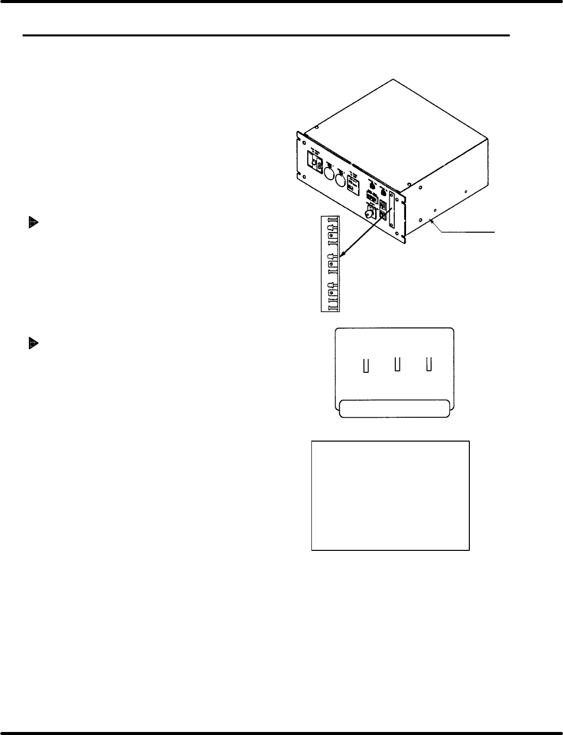
1. Remove the cover from the power source
unit
2. Check power supply voltage between 5 pin
(+5V) and 6 pin (0V)of CHU OUT (CN2 on
insertion detection amplifier board with the
voltmeter.
Distortion gauge amplifier board
jumper setting
1. Remove the distortion gauge amplifier board
from the power source unit, and select
clinch method (N or T clinch) with jumper
setting.
=REFERENCE=
x N clinch
JP1: 2 − 3 short
JP2: 2 − 3 short
JP3: 1 − 2 short
x T clinch
JP1: 1 − 2 short
JP2: 1 − 2 short
JP3: 2 − 3 short
Power source
unit
Reference 2.5 5.0
Ch1 3 2
Relation between distortion
gauge and insertion pitch
I/O address
Ch1: 0064
Ch2: 0065
Ch3: 0066
Panadac−791