Q170226E01.pdf - 第115页
RH5 5.3 X−Y T able Origin and Over Limit Check and Adjustment SERVICE MANUAL 5.3−4 DA3SEC−83−8KO−A0 Checking/Adjusting X−Y table limit divider 1. Select “NC AXIS MOVE CHECK” o “NC AXIS JOG CHECK” via the main control pan…
5.3 X−Y Table Origin and Over Limit Check and Adjustment
SERVICE MANUAL
RH5
5.3−3
DA3SEC−83−8KO−A0
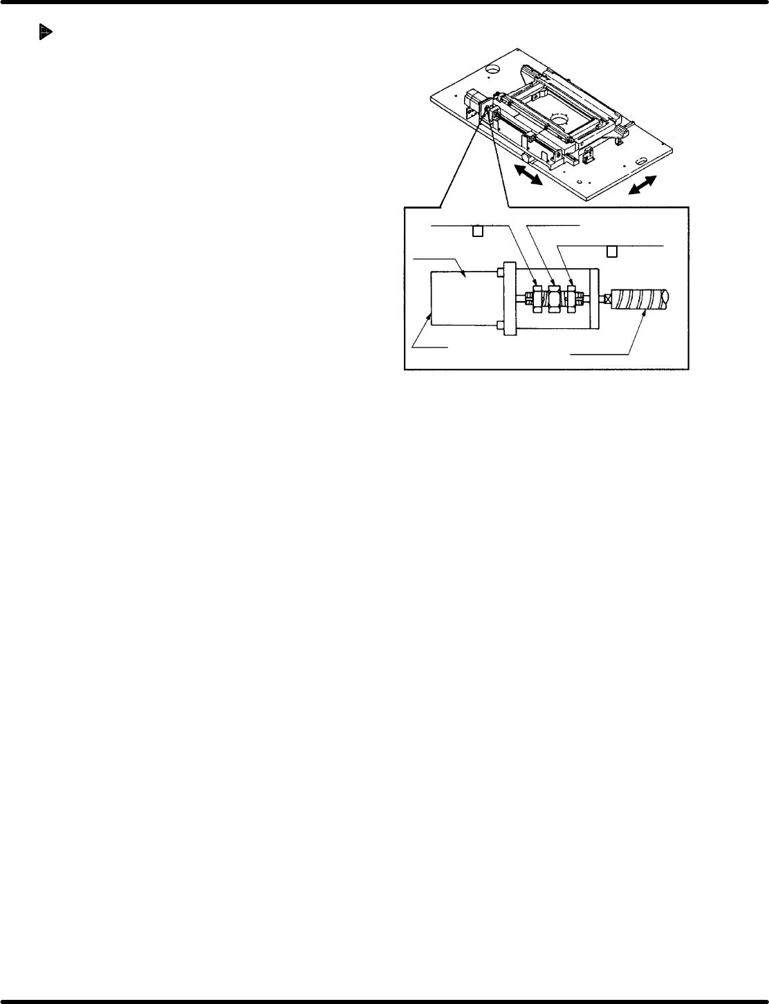
Adjusting origin position
1. Change the CH4 (speed loop gain) of the X
axis (Y axis) driver from 200 to 100.
2. Turn OFF the power and turn it back ON.
3. Return the X−Y table to its origin by hand
and move it to the data position created in
step 4 in ‘Checking origin position’.
4. Disengage the N coupling.
5. Move the X−Y table manually to which the
guide pin comes out of the origin board by
turning the hand wheel.
6. Return the hand wheel to its origin and then
tighten the N coupling.
7. Change the CH4 (speed loop gain) of the X
axis (Y axis) driver from 100 to 200.
8. Turn OFF the power and turn it back ON.
9. Check the X−Y table again by following
steps 7 and 8 in ‘Checking origin position’.
Motor side nut
(17 mm )
Ball screw side nut
(17 mm )
N coupling
Motor
LED
Ball screw
RH5
5.3 X−Y Table Origin and Over Limit Check and Adjustment
SERVICE MANUAL
5.3−4
DA3SEC−83−8KO−A0
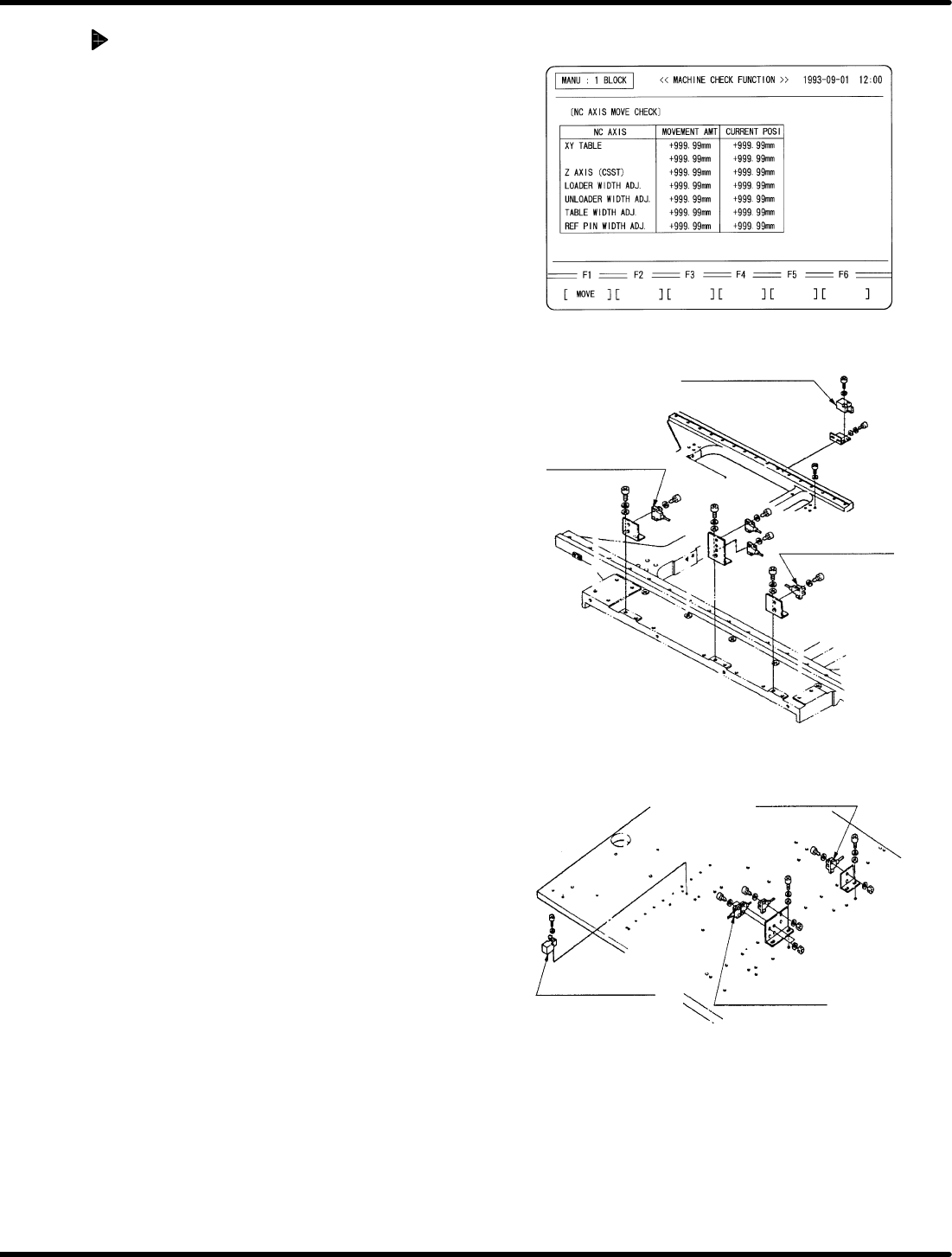
Checking/Adjusting X−Y table limit
divider
1. Select “NC AXIS MOVE CHECK” o “NC AXIS
JOG CHECK” via the main control panel. Input
the distance (numeric value) up to the X and
Y−axis limit sensors and move the axes to make
sure the sensors light up accordingly.
<M>
X−axis limit sensor:
Plus limit
(+273.40 to +273.50)
Minus limit
(−183.40 to −183.50)
Y−axis limit sensor:
Plus limit
(+1.40 to +1.50)
Minus limit
(−256.40 to −256.50)
<LL>
X−axis limit sensor:
Plus limit
(+346.40 to +346.50)
Minus limit
(−256.40 to −256.50)
Y−axis limit sensor:
Plus limit
(+1.40 to +1.50)
Minus limit
(−386.40 to −386.50)
2. If these sensors do not detect or detect early,
adjust the sensors by moving the sensor bracket.
=CHECK=
x After making adjustment, move the axes
again and check they are detected at the
sensors and that the axes move no more
than the specified distance (displayed
numeric value).
x Check that the slit plates and each
photonimic are not obstructed in any way.
X−axis safety limit
switch
X−axis + limit
sensor
X−axis − limit
sensor
Y−axis − limit
sensor
Y−axis + limit
sensor
Y−axis safety limit
switch
5.4 Loader/Unloader Belt Replacement and Adjustment
SERVICE MANUAL
RH5
5.4−1
DA3SEC−83−8LO−A0
5.4 Loader/Unloader Belt Replacement and Adjustment
DA3SEC−83−8LO−A0
Sentence No.
When to perform
x When the belt pops or cut
x When the belt slips due to wear
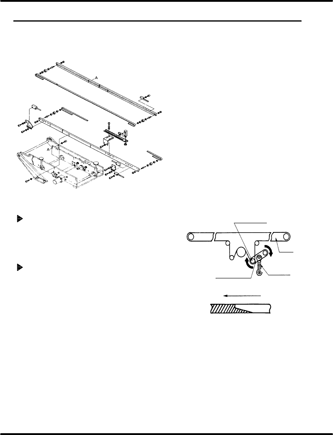
Belt removal
1. Remove the spring and raise the tension
lever. Then remove the belt by hand.
Attaching a new belt
1. Set a new belt on the rails and hook it to the
tension roller, observing to the seam.
=CHECK=
x Make sure the belt seam is facing as
shown on the left.
x When one or more belts need replacing
due to wear, replace all four belts at a
time.
Tension roller
Tension lever
Spring
Belt
Direction of rotation
Belt seam