Q170226E01.pdf - 第323页
RH5 8.3 List of Jumper Switch Settings SERVICE MANUAL 8.3−26 DA3SEC−85−540−B0 (1) TTY This is a serial port used for both TTY and the keyboard. The TTY has switches for changing from normal signal to TTY applicable signa…
8.3 List of Jumper Switch Settings
SERVICE MANUAL
RH5
8.3−25
DA3SEC−85−540−B0
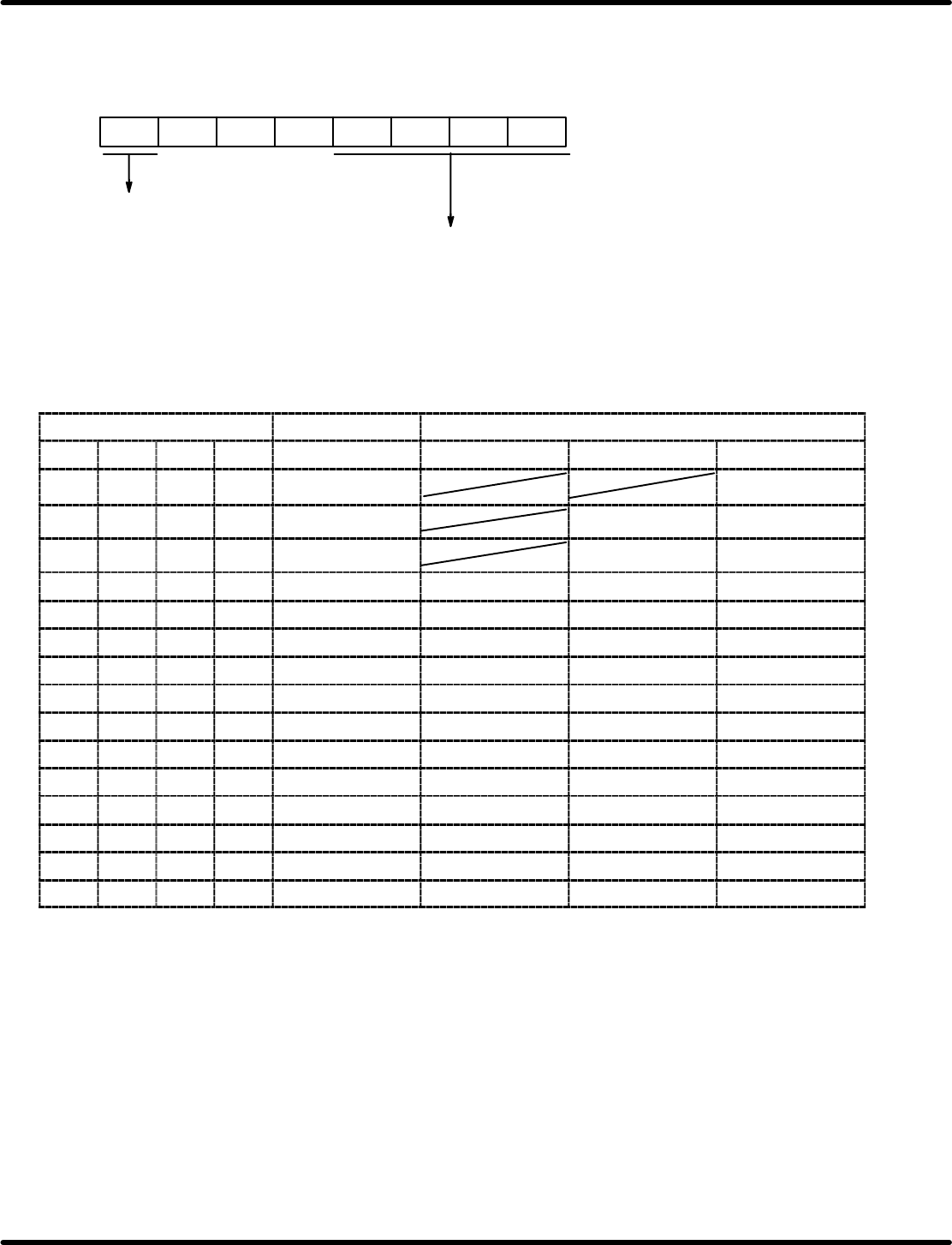
The baud rate setting register sets the desired baud rate both when using the internal clock and using the
ST1 output.
Standard clock setting is 2.4576 MHz. Bit configuration is given below.
Counter reset
Baud rate setting
0: Normal operation
1: Counter reset
B7 B6 B5 B4 B3 B2 B1 B0
0
0
0
Relationship between register setting and baud rate
Baud rate setting register f
RVC
Baud rate (bps)
B3 B2 B1 B0 f
RVC
1/1 mode 1/16 mode 1/64 mode
0 0 0 0 1.2288 MHz
0 0 0 1 614.4 kHz 38400 9600
0 0 1 0 307.2 kHz 19200 4800
0 0 1 1 153.6 kHz 153600 9600 2400
0 1 0 0 76.8 kHz 76800 4800 1200
0 1 0 1 38.4 kHz 38400 2400 600
0 1 1 0 19.2 kHz 19200 1200 300
0 1 1 1 9600 Hz 9600 600 150
1 0 0 0 4800 Hz 4800 300 75
1 0 0 1 2400 Hz 2400 150
1 0 1 0 1200 Hz 1200 75
1 0 1 1 600 Hz 600
1 1 0 0 300 Hz 300
1 1 0 1 150 Hz 150
1 1 1 0 75 Hz 75
=REFERENCE=
Crossed out blocks can’t be used because they don’t satisfy requirements between f
RVC,
f
TRN
and
f
CLK.
RH5
8.3 List of Jumper Switch Settings
SERVICE MANUAL
8.3−26
DA3SEC−85−540−B0
(1) TTY
This is a serial port used for both TTY and the keyboard.
The TTY has switches for changing from normal signal to TTY applicable signal. The keyboard for the
PC9800 Series (NEC) can be used for this connection.
Switches and jumpers are explained in the following.
Jumpers and Switches
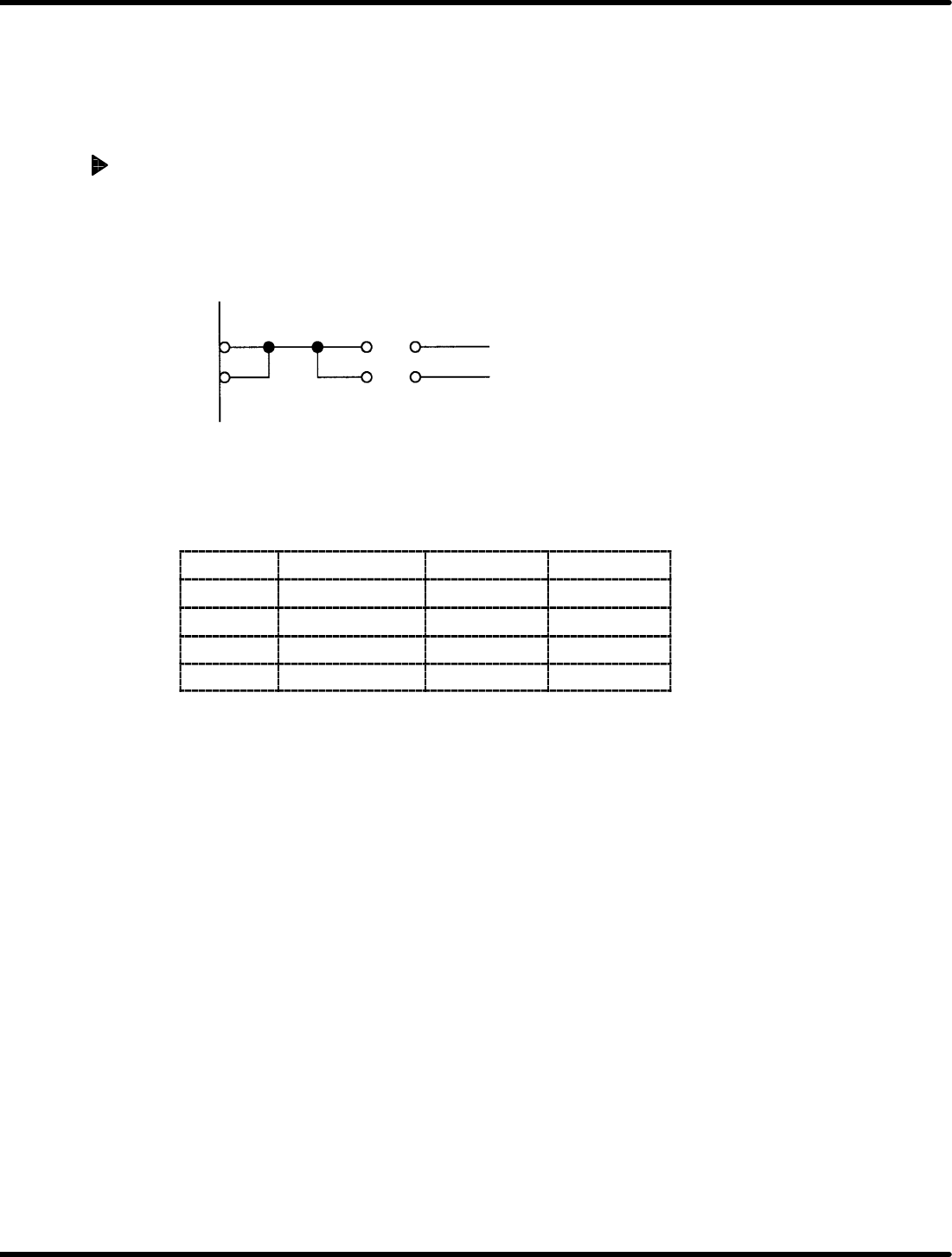
1. Transmission clock switch
The transmission clock can be switched with JP5.
(It is possible to use the baud rate generator inside.)
TXC 1 307.2 KHz
RXC 2 OUT2 for 8254
JP5
2. TTY/keyboard switching
Switching between TTY (RS−232C or current loop) and the keyboard can be done with JP6, 8, 15 and
16.
JP name
Signal name TTY Keyboard
JP6 CTS A−C * B−C
JP8 RTS A−C B−C
JP15 TXD A−C B−C
JP16 RXD A−C B−C
=REFERENCE=
x When the CTS signal in the TTY is not used, it is necessary to connect B−C of JP6 and set CTS
to “L” (send enabled).
8.3 List of Jumper Switch Settings
SERVICE MANUAL
RH5
8.3−27
DA3SEC−85−540−B0
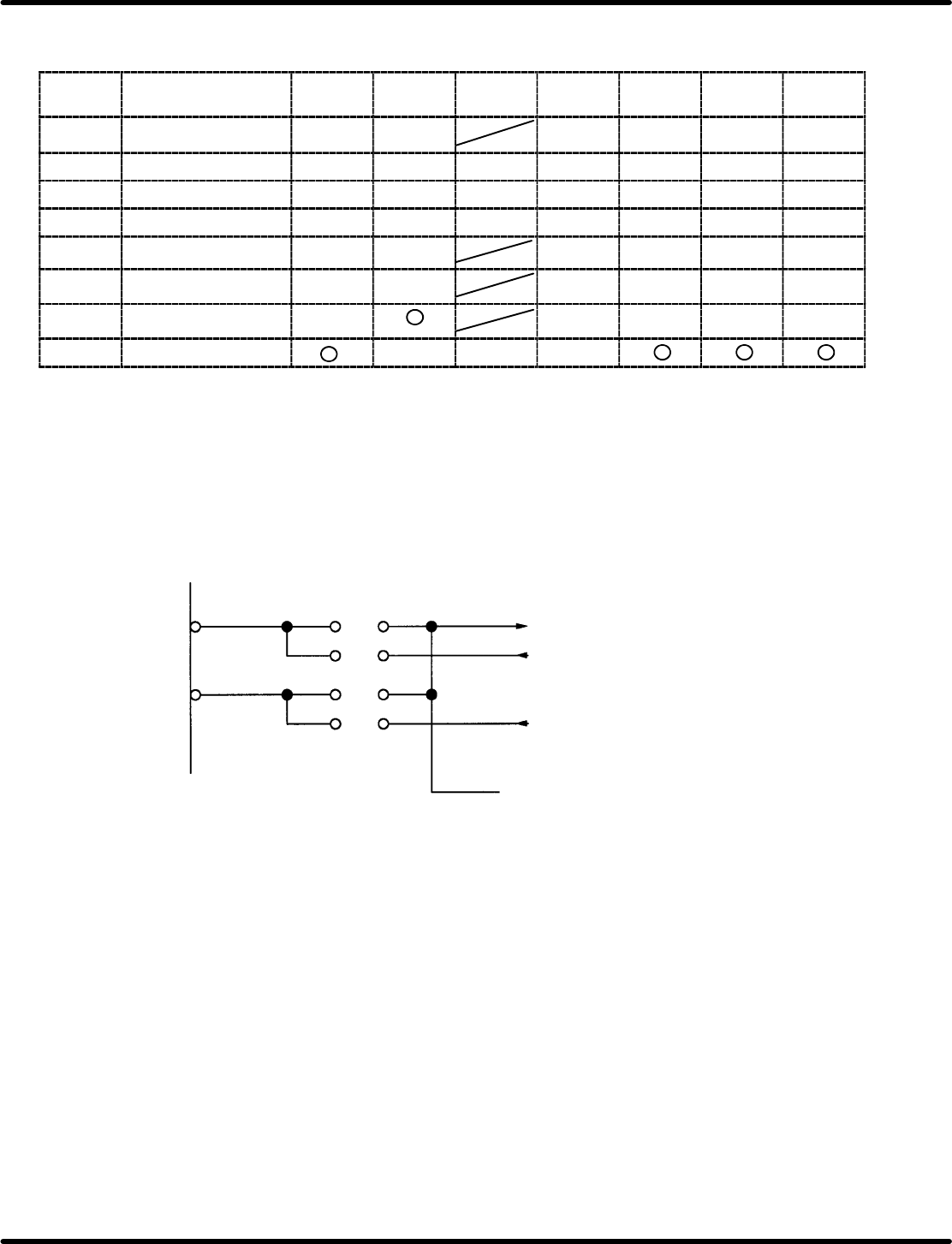
3) TTY type switching (transmission method)
TTY type can be switched and used with SW6−11 and JP13 and 14.
SW or
jumper
Signal name Current
loop
TTL RS232C ASR33 ASR43 CITIZEN CASIO
SW6 READER START 1 2 3 3 2 2
SW7 OUTPUT DATA 1 2 4 3 1 1 1
SW8 INPUT DATA 1 2 4 3 1 1 1
SW9 INPUT DATA 1 2 4 3 1 1 1
SW10 DATA BUSY 1 2 3 3 1 1
SW11 DATA BUSY 1 2 3 3 1 1
JP13 READER START u u u u
u
JP14 INPUT DATA u u u
ON bit numbers are given for switches. Do not set more than one switch ON at a time.
JP setting is indicated as for sort, u for open. Disregard crossed out blocks.
(2) HOST
This is a RS−232C specified serial port for linking up with the host computer.
The transmission clock can be switched with JP1 and 2.
(It is possible to use the internal baud rate generator.)
OUT2 for 8254
TXC
RXC
JP2
JP1
ST1
ST2
RT
1
2
1
2