Q170226E01.pdf - 第217页
RH5 5.34 A x i s H eight Check and Adjustment SERVICE MANUAL 5.34−4 DA3SEC−83−9S0−A0 = MEMO =
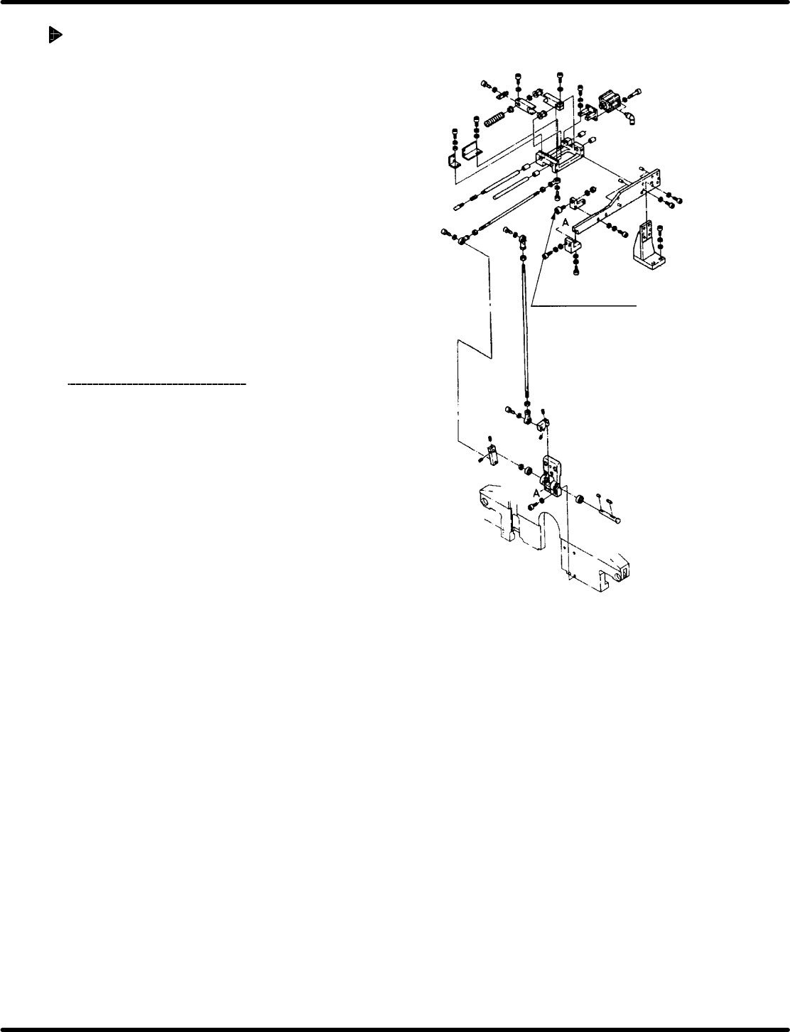
Cam follower for Z
axis holder support
5.34 Axis Height Check and Adjustment
SERVICE MANUAL
RH5
5.34−3
DA3SEC−83−9S0−A0
Adjusting Z axis height (Lowering
the Z axis)
1. Disengage the bolt stopper.
2. Sandwich the thickness gauge (has the
height to be lowered) between the bolt
stopper and holder bracket.
3. Retighten the bolt stopper.
4. Disengage the Z axis holder bracket (4− M8).
5. Tap the Z axis holder bracket from above
and make sure that 0.03 mm thickness
gauge can ’t be fit in.
6. Retighten the Z axis holder bracket (4− M8).
7. Check the tape waste again.
=CHECK=
Ensure that either of the cam follower
(x 2) for supporting the Z axis holder
mounted on the feed plate fit the Z
axis holder.
(When adjusting the Z axis height, do
the cam follower position as well.)

RH5
5.34 Axis Height Check and Adjustment
SERVICE MANUAL
5.34−4
DA3SEC−83−9S0−A0
= MEMO =

5.35 Mechanical V alve Replacement and Adjustment
SERVICE MANUAL
RH5
5.35−1
DA3SEC−83−9T0−A0
5.35 Mechanical Valve Replacement and Adjustment
DA3SEC−83−9T0−A0
Sentence No.
Replacing mechanical valve
1. Turn OFF the power to the machine and cut
off air supply.
2. Remove the fitting bolt (2−M4) of the
mechanical valve.
3. Disconnect the air hose and detach the
mechanical valve.
=CHECK=
Mark the air hose before removing.
4. Attach a new mechanical valve in the reverse
order.
=CHECK=
Use a dedicated mechanical valve for
RH5. (Product No.: N413AXT752A5)
Adjusting mechanical valve
1. Press “SEMI” and “1BLOCK” on the main
control panel.
2. Turn the hand wheel to adjust so that the
roller of the mechanical valve fit to the cam
groove.
=REFERENCE=
T iming of the respective chuck groove is as
follows:
x Transfer chuck: Approx. 80−280q
x Insertion chuck: Approx. 80−180q
x Guide chuck: Approx. 130−190q
Timing varies depending on the groove.