Q170226E01.pdf - 第325页
RH5 8.3 List of Jumper Switch Settings SERVICE MANUAL 8.3−28 DA3SEC−85−540−B0 (3) SIO 1 and 2 This is a serial port dedicated to RS232C for general purpose use. The transmission clock can be switched with JP18, 19 and 20…
8.3 List of Jumper Switch Settings
SERVICE MANUAL
RH5
8.3−27
DA3SEC−85−540−B0
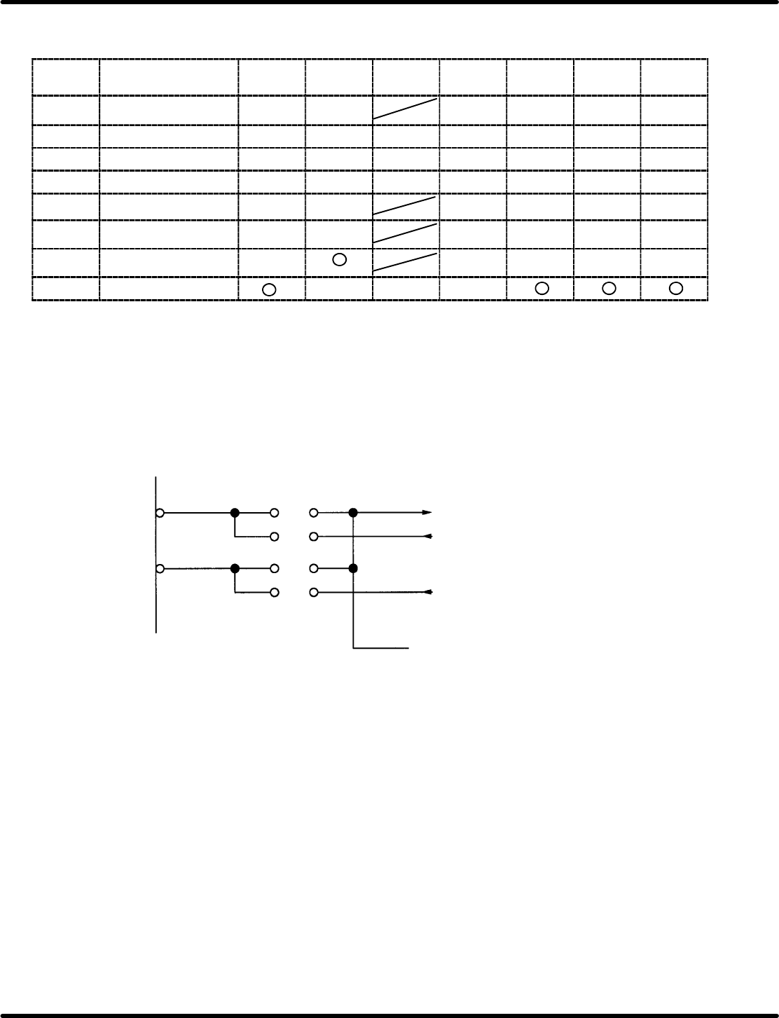
3) TTY type switching (transmission method)
TTY type can be switched and used with SW6−11 and JP13 and 14.
SW or
jumper
Signal name Current
loop
TTL RS232C ASR33 ASR43 CITIZEN CASIO
SW6 READER START 1 2 3 3 2 2
SW7 OUTPUT DATA 1 2 4 3 1 1 1
SW8 INPUT DATA 1 2 4 3 1 1 1
SW9 INPUT DATA 1 2 4 3 1 1 1
SW10 DATA BUSY 1 2 3 3 1 1
SW11 DATA BUSY 1 2 3 3 1 1
JP13 READER START u u u u
u
JP14 INPUT DATA u u u
ON bit numbers are given for switches. Do not set more than one switch ON at a time.
JP setting is indicated as for sort, u for open. Disregard crossed out blocks.
(2) HOST
This is a RS−232C specified serial port for linking up with the host computer.
The transmission clock can be switched with JP1 and 2.
(It is possible to use the internal baud rate generator.)
OUT2 for 8254
TXC
RXC
JP2
JP1
ST1
ST2
RT
1
2
1
2
RH5
8.3 List of Jumper Switch Settings
SERVICE MANUAL
8.3−28
DA3SEC−85−540−B0
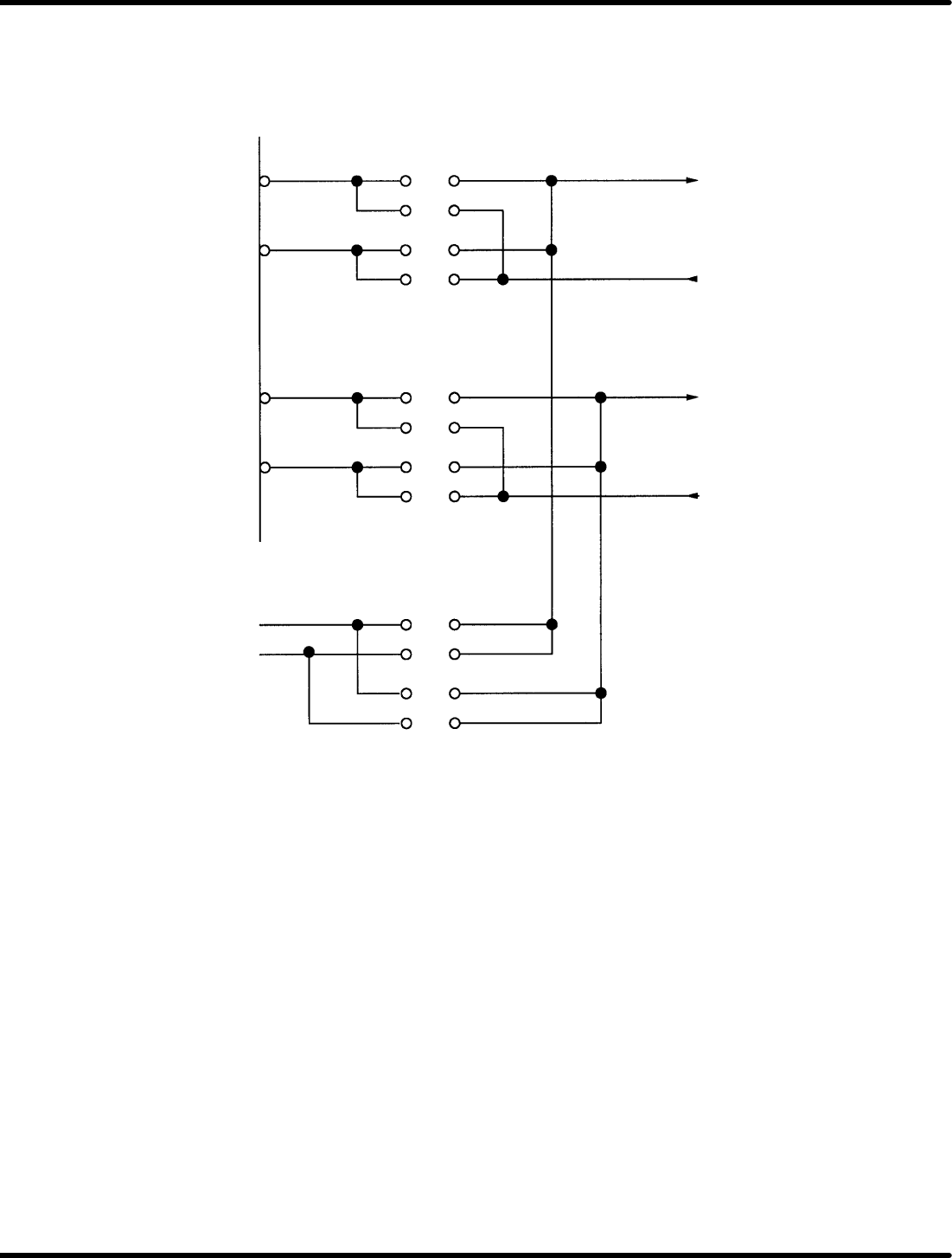
(3) SIO 1 and 2
This is a serial port dedicated to RS232C for general purpose use.
The transmission clock can be switched with JP18, 19 and 20.
(It is possible to use the internal baud rate generator inside.)
TXC1 1 ST1 − 1
2
RXC1 3 ST2 − 1
4
TXC2 1 ST1 − 2
2
RXC2 3 ST2 − 2
4
307.2KHz 1
OUT2 for 8254 2
3
4
JP19
JP20
JP18
8.3 List of Jumper Switch Settings
SERVICE MANUAL
RH5
8.3−29
DA3SEC−85−540−B0
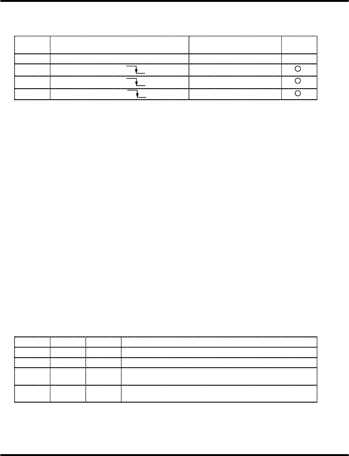
NMI and RESET
From this board, it is possible to notify the NMI (CPU) of the four factors making up the non−maskable
interrupt. Furthermore, factors can be confirmed using mask control and status data.
NMI
factor
Source address Status data Mask
ON/OFF
SW Push SW SW2 on board front D3 bit from port 22 H u
PFIN P2 bus A28 D2 bit from port 22 H
WDT P2 bus C28 D1 bit from port 22 H
ERROR 8 for JP11 D0 bit from port 22 H
This board is initialized with the following signals.
1. Reset circuit at power ON
Using the MB3771, a reset pulse can be transmitted approximately 100 msec when
power is ON or a voltage drop down to approx. 4.3V.
2. Push SW (Board front SW1)
Using the MB3771, a reset pulse can be transmitted for about 100 msec when SW1 is
pressed or after having been pressed..
3. PR bus INIT * (A6)
4. P2 bus RESET * (C27)
While INIT * and RESET * on the P2 bus line are set to “L”, the reset state is ON.
Bus interface setting
(1) BCLK: JP4
Short: BCLK (9.8304 MHz) is output to B6 of P2.
Open: BCLK is not output. (Output comes from another master instead.)
(2) CCLK: JP3
Short: CCLK (9.8304 MHz) is output to A12 of P2.
Open: CCLK is not output. (Other master will be output.)
(3) BPRO: JP10
Short: BPRO is output to C6 of P2.
Open: BPRO is not output.
(4) Bus release: JP9
JP9
CBRQ ALWAYS Description
B−C HorL L Bus is released at the end of every bus cycle.
Open L H Bus is released at the end of every bus cycle regardless of priority.
Open H H
Bus is not released until either CBRQ= “L” changes into BPRN= “H”
or the CPU is assumed to a halt.
A−C
HorL Connected
to reset
Bus is not released until either the bus master priority changes to
BPRN= “H” or the CPU is assumed to a halt.