Q170226E01.pdf - 第199页
Attach the brackets as shown in the figure. Bracket Bracket Camera lens Camera Insertion head Head flange Bolt (1) Bolt (2) 90.0 mm Bracket (1) 150 H 1m m PC board (thickness t = 1.6 mm) RH5 5.32 Setting Offset V alues S…
5.32 Setting Offset Values
SERVICE MANUAL
RH5
5.32−3
DA3SEC−83−9Q0−A0
Initial setting of individual
machine data
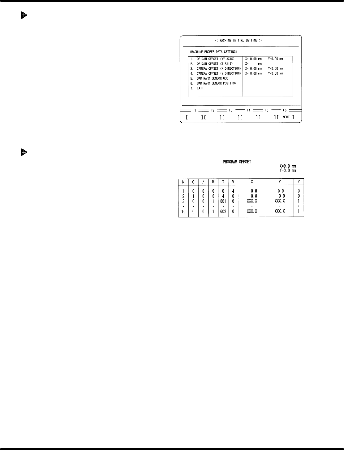
1. Enter 0 in origin offset and camera offset for
individual machine setting screen.
x Press ESC.
x Press F6. (MORE)
x Press F1 (MACHINE INITIAL SETTING)
x Press F2 (INDIVIDUAL MACHINE DATA)
x Enter 0 in ORIGIN OFFSET (X, Y) and
CAMERA OFFSET (X, Y).
=REFERENCE=
Customer’s production board can also
be used for adjustment if origin board is
unavailable.
When using a customer’s board
1. Select two insertion directions X and Y for
the board and create an NC data that allows
only the selected two points to be operated.
=REFERENCE=
Select two X and Y positions near the
center of the PC board.
=CHECK=
Enter /7 (unconditional skip) in the
unnecessary blocks or copy an editing
NC data and delete unnecessary part of
the data.
2. Perform teaching with the NC data created
in step 1 and create data so that the guide
pin may be aligned with the center of the
board hole, regarding both X and Y direction
data.
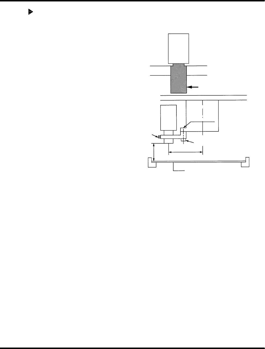
Attach the brackets as
shown in the figure.
Bracket Bracket
Camera lens
Camera
Insertion head
Head flange
Bolt (1)
Bolt (2)
90.0 mm
Bracket (1)
150 H
1mm
PC board
(thickness t = 1.6 mm)
RH5
5.32 Setting Offset Values
SERVICE MANUAL
5.32−4
DA3SEC−83−9Q0−A0
Camera installation
1. Attach bracket (1) to the head flange and
secure with bolt (1).
2. Install camera to the bracket (1).
=REFERENCE=
Camera height
x 148.4 mm from the board top (When
board thickness is 1.6 mm)
x 150.0 mm from the bottom of board
(lower side of rail)
Camera installation direction
x Install the camera so that the model
number label can be seen from the
front side.
x Recognition camera setting
(Teli camera only)
=CHECK=
x As for NEC camera, recognition
camera setting will not be
performed.
5.32 Setting Offset Values
SERVICE MANUAL
RH5
5.32−5
DA3SEC−83−9Q0−A0
Camera position adjustment
1. Set the prepared board onto the XY table.
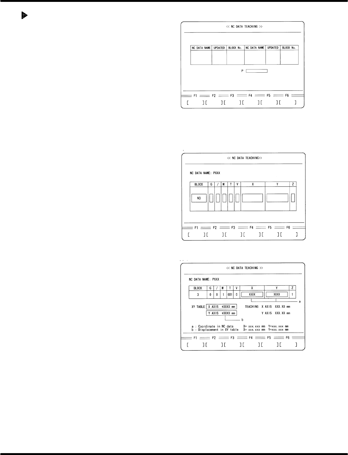
2. Select teaching mode and choose the
created NC data.
x Press ESC twice.
x Press F6 (MORE).
x Press REQ.
x Press F3 (NC DATA TEACHING).
x Move the cursor to the created NC data
using npkeys.
x Press ENTER.
x Press F1 (YES).
3. Move the XY table to the No.3 block
insertion potion in the NC data.
x Move the cursor to N3 block using np
keys.
x Press ENTER.
x Press F1 (MOVE).
4. Perform XY teaching for X direction
insertion so that the guide pin may be
aligned with the center of the insertion hole.
5. Write down the coordinate value (a) and XY
table displacement(b) displayed on the NC
DATA TEACHING screen.