Q170226E01.pdf - 第169页
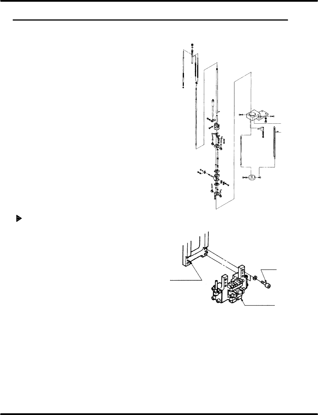
Left Center Right Installation nut Center pin selector rod Right pin selector rod Cartridge Spring holder Guide pin rod Selector unit Selector unit lock pin Cut & clinch body Guide rod Positioning pin Bolt B RH5 5.21…
Positioning pin
Bolt A
Guide chuck
5.21 Selector Unit Lead Guide Pin Replacement
SERVICE MANUAL
RH5
5.21−1
DA3SEC−83−9D0−A0
5.21 Selector Unit Lead Guide Pin Replacement
DA3SEC−83−9D0−A0
Sentence No.
When to perform
x When the guide pin does not rise
vertically.
x When the guide pin gets caught on the
insertion hole.
Required tools
x Allen wrench
Guide chuck unit removal
1. Loosen bolt A (x 4) and remove the guide
chuck unit.
Left
Center
Right
Installation nut
Center pin selector
rod
Right pin selector
rod
Cartridge
Spring holder
Guide pin rod
Selector unit
Selector unit lock pin
Cut & clinch body
Guide rod
Positioning pin
Bolt B
RH5
5.21 Selector Unit Lead Guide Pin Replacement
SERVICE MANUAL
5.21−2
DA3SEC−83−9D0−A0
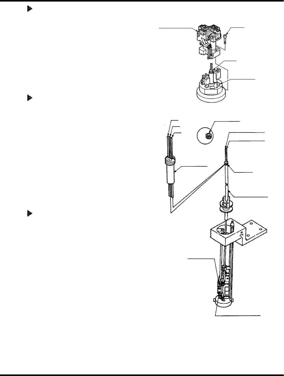
Cut & clinch unit removal
1. Loosen bolt B (x 2) and remove the cut &
clinch unit.
2. Remove any waste or cut scraps from
inside the dust cover.
Guide pin removal
1. Bring the pin at the 200q on the digital
sequence timer.
2. Loosen the installation nut fixing the
cartridge in place.
3. Pull the selector unit lock pin until there is
play and lift the selector unit upwards.
=CHECK=
Be careful the guide pins do not
contact the insertion head.
4. Remove the guide pins from the selector
rod groove.
Guide pin replacement
1. Remove the spring holder.
2. Replace the guide pins.
3. Insert the lower end of the new right and
center guide pins into the selector rod
groove.
4. Pull the selector unit lock pin until there is
play, and lower the unit by hand.
=REFERENCE=
There are two types of guide pins. Be
careful when replacing them.
Cut & clinch body
Bolt B
Guide rod
Positioning pin
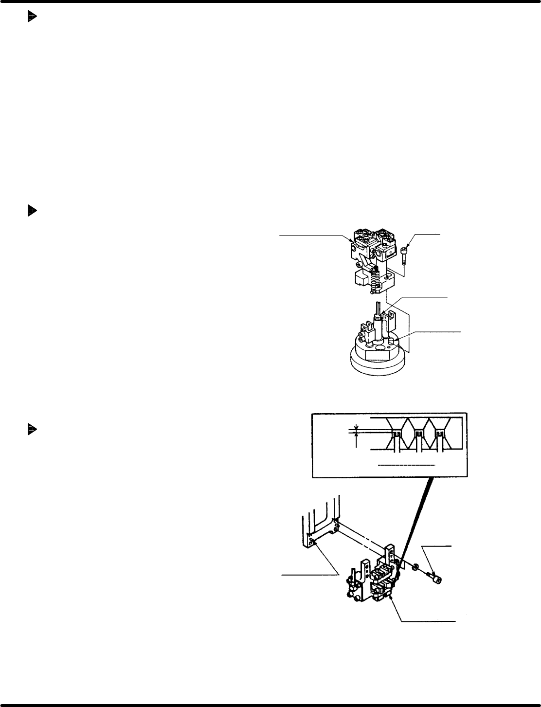
Allowable
range
0.3 − 0.5
mm
Guide pin
height
Bolt A
Positioning pin
Guide chuck
5.21 Selector Unit Lead Guide Pin Replacement
SERVICE MANUAL
RH5
5.21−3
DA3SEC−83−9D0−A0
Setting the cartridge
1. Attach the cartridge to the guide pin rod.
2. Tighten the installation nut fixing the
cartridge in place.
=REFERENCE=
T ighten the installation nut fixing the
cartridge with the nipper not to be
loosened by hand.
Setting the cut & clinch body
1. Align the cartridge with the positioning pin and
fix it in place with bolt B (x 2).
Setting the guide chuck unit
1. Align the guide chuck unit with the
positioning pin and attach it.
2. Check that the guide pin height is correct
and in the correct position. Then fix it in
place with bolt A (x 4).