Q170226E01.pdf - 第270页
7.2 AC Servomotor Adjustment SERVICE MANUAL RH5 7.2−15 DA3SEC−84−300−A0 Parameter No. Name Default Cn−16 W ait time from SV OFF to brake command 50 50 Cn−17 T orque command filter constant (4) (4) Cn−18 Outer torque limi…
RH5
7.2 AC Servomotor Adjustment
SERVICE MANUAL
7.2−14
DA3SEC−84−300−A0
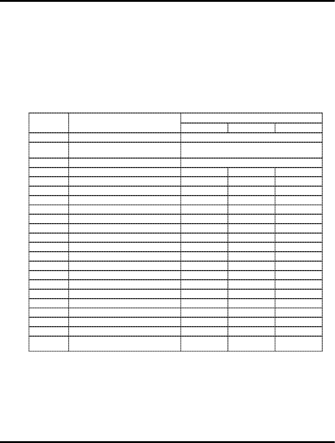
AC Motor Driver Setting T able (RH5 (M) <NM−8844R>)
=REFERENCE=
x Values ( ) are required to fine adjust.
x Adjust Cn−17 if the motor oscillates after the table has stopped.
x Use the motor driver as follows:
X axis: DR2−02ACY27, Y axis: DR2−04ACY27, Z axis (62−feeder):
DR2−08ACY27, Z axis (80−feeder): CACR−SR15VE13S, Cam shaft:
CACR−SR20VE17SY19
x Adjust the offset of Cn−00−003 via the digital operator. (Refer to ‘7.3’.)
x Values marked with an asterisk show new parameters corresponding to the positioning delay error.
x After setting Cn−01 and Cn−0A, turn OFF the power to the machine.
X/Y/Z axis (62−feeder)
Parameter
N
Name Default
No.
X axis Y axis Z axis
Cn−00−003 Offset
Cn−01 Memory switch 1 FFDCBA9876543210
0001000000000000
Cn−02 Memory switch 2 0000000000000000
Cn−03 Speed command gain 1300 1300
Cn−04 Speed loop gain (140) (150)
Cn−05 Consult speed loop integrated * 50000 * 50000
Cn−06 Emergency stop torque 300 300
Cn−07 Soft start time (acceleration) 0 0
Cn−08 Normal rotation torque limit 300 300
Cn−09 Reverse rotation torque limit 300 300
Cn−0A Encoder pulse dividing ratio 1000 1000
Cn−0B Rotation detection level 20 20
Cn−0C Mode switch (torque command) 200 200
Cn−0D Mode switch (speed command) * 100 * 100
Cn−0E Mode switch (acceleration command) 0 0
Cn−0F Mode switch (deviation pulse) 0 0
Cn−10 JOG speed 500 500
Cn−11 Encoder pulse count 2048 2048
Cn−12 Delay time from brake command to SV OFF 0 0
Cn−13 Torque command gain 30 30
Cn−14 Speed control at torque control I 4500 4500
Cn−15 Speed level at which output brake
command
100 100
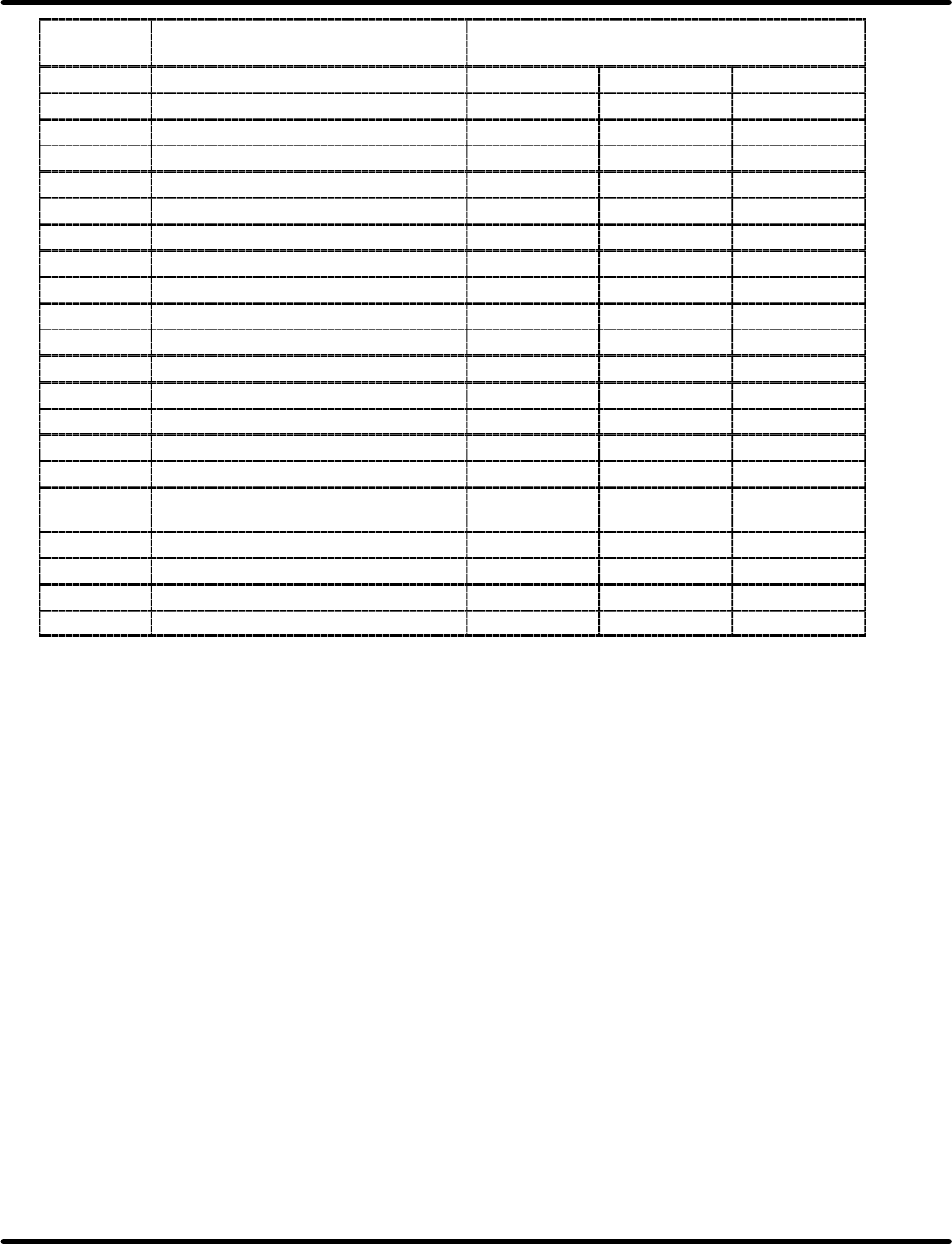
7.2 AC Servomotor Adjustment
SERVICE MANUAL
RH5
7.2−15
DA3SEC−84−300−A0
Parameter
No.
Name Default
Cn−16 Wait time from SV OFF to brake command 50 50
Cn−17 Torque command filter constant (4) (4)
Cn−18 Outer torque limit on normal rotation side 100 100
Cn−19 Outer torque limit reverse rotation side 100 100
Cn−1A Position loop gain 40 40
Cn−1B Positioning complete width 7 7
Cn−1C Bias 0 0
Cn−1D Feed forward 0 0
Cn−1E Over flow 1024 1024
Cn−1F Speed command gain 2 200 200
Cn−20 Speed command gain switch voltage 4 4
Cn−21 300 300
Cn−22 Speed coincidence signal output width 10 10
Cn−23 Soft start time (deceleration) 0 0
Cn−24 Electronic gear ratio (numerator) 4 4
Cn−25 Electronic gear ratio (denominator) 1 1
Cn−26 Constant at positioning command speed
chaging
0 0
Cn−27 Feed forward filter 0 0
Cn−28 Speed loop compensating constant 0 0
Cn−29 Zero clamp level 10 0
Cn−2A Outer PG pulse count 2048 2048
RH5
7.2 AC Servomotor Adjustment
SERVICE MANUAL
7.2−16
DA3SEC−84−300−A0
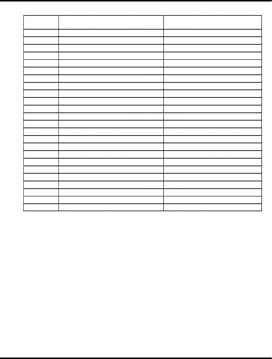
Z axis (80−feeder)
Parameter
No.
Name Default
Cn−00−0003 Offset
Cn−01 Memory switch 1 * 0001000000001100
Cn−02 Memory switch 2 0000000000000000
Cn−03 Speed command gain 1400
Cn−04 Speed loop gain (180)
Cn−05 Constant speed loop integrated *50
Cn−06 Emergency stop torque 269
Cn−07 Soft start time (acceleration) 0
Cn−08 Normal rotation torque limit 269
Cn−09 Reverse rotation torque limit 269
Cn−0A Encoder pulse dividing ratio 640
Cn−0B Rotation detection level 20
Cn−0C Mode switch (torque command) * 200
Cn−0D Mode switch (speed command) *50
Cn−0E Mode switch (acceleration command) 0
Cn−0F Zero clamp level 10
Cn−10 JOG speed 100
Cn−11 Encoder pulse count 2048
Cn−12 Delay time from brake command to SV OFF 20
Cn−13 Torque command gain 30
Cn−14 Speed control at torque control I 4000
Cn−15 Speed level at which output brake command 100
Cn−16 Wait time from SV OFF to brake command 50
Cn−17 Torque command filter constant (15)