Q170226E01.pdf - 第238页
RH5 6.1 Checking Maintenance Precision SERVICE MANUAL 6.1−1 DA3SEC−89−010−A0 6.1 Checking Maintenance Precision DA3SEC−89−010−A0 Sentence No. No. Check item Description Illustration Criteria Measured value 1 Prim…

RH5
SERVICE MANUAL
6.0−4
DA3SEC−89−000−A0
= MEMO =
RH5
6.1 Checking Maintenance Precision
SERVICE MANUAL
6.1−1
DA3SEC−89−010−A0
6.1 Checking Maintenance Precision
DA3SEC−89−010−A0
Sentence No.
No. Check item
Description
Illustration Criteria
Measured
value
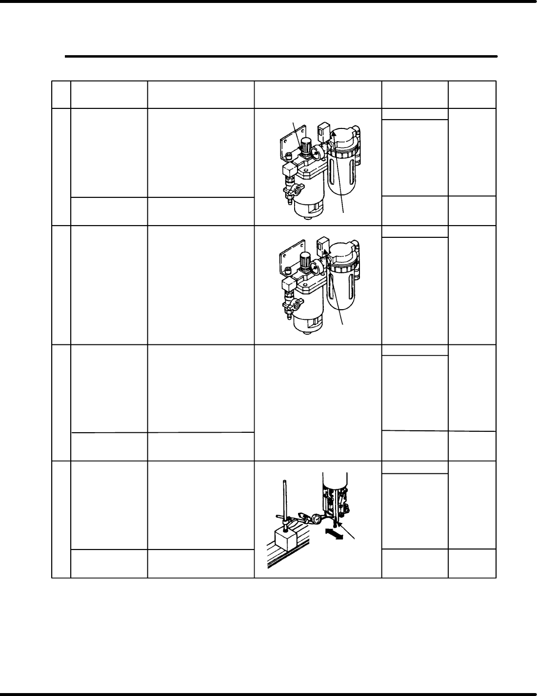
1
Primary air
pressure setting
Bolt
Set the pressure reducing
valves of the air units (x 3).
* Check if the specified oil
is supplied.
* Check if the oil drips
once per five minutes.
* Check if the units have
been locked after setting.
Setting knob
2
3
4
Visual check
Visual check
0.45 to 0.55 MPa
0.35 to 0.40 MPa
0.27 to 0.33 MPa
0.07 to 0.09 MPa
0.23 to 0.28 MPa
Pressure SW
setting of primary
air pressure
Air pressure setting
Bolt
M5 x 3
M6 x 4
M8 x 4
Bolt
Setting knob
Set the pressure SW.
* Connect the connector
at the same time.
* Check the functions.
OK/NG
OK/NG
OK/NG
0to0.40mm
White marker
check
mm
MPa
MPa
Pickup test
Insertion chuck low pressure
Pusher low pressure
Pusher high pressure
* Check if the units have
been locked after setting.
* Paint marker
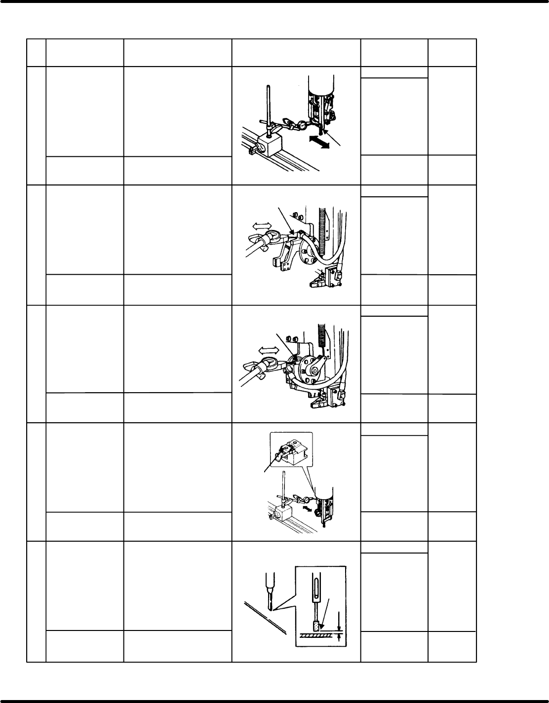
Insertion head
swing precision
(X direction)
To be measured at
210
Measure the swing precision
of the guide chuck
installation surface by
moving the table in Y
direction.
Measure the value within the
range of 50 mm.
Set the pressure reducing
valves of the chuck
pressure, pusher low
pressure and pusher high
pressure.
MPa
MPa
MPa
Measurement
surface
Pressure SW
Drip control valve
Pressure reducing valve
6.1 Checking Maintenance Precision
SERVICE MANUAL
RH5
6.1−2
DA3SEC−89−010−A0
No.
Check item
Description
Illustration
Criteria
Measured
value
5
6
7
8
9
Bolt
M6 x 2
M8 x 4
OK/NG
0to0.40mm
White marker
check
mm
Pickup test
Insertion head
swing precision
(Y direction)
To be measured at
210
Bolt
Insertion chuck
parallelism
To be measured at
0
M4 x 2
Measure the swing precision
of the guide chuck installation
surface by moving the table
in X direction.
Measure the value within the
range of 50 mm
(Measure the value with the
Y lock unit engaged.)
Measure the parallelism
when the insertion chuck is
at the transfer position by
moving the table.
Measure the value within the
range of 25 mm.
mm
mm
mm
mm
0to0.03mm
0to0.03mm
0to0.03mm
0to0.5mm
Thickness gauge
Bolt
M4 x 2
Insertion chuck
perpendicularity
To be measured at
210
Measure the perpendicularity
when the insertion chuck is
angled at 210 by moving the
table.
Measure the value within the
range of 25 mm.
Measurement
surface
Measurement
surface
Measurement
surface
Measurement
surface
Pickup test
Pickup test
Pickup test
White marker
check
White marker
check
White marker
check
White marker
check
Bolt
M6 x 1
Insertion chuck axis
perpendicularity
To be measured at
210
Measure the perpendicularity
when the insertion chuck is
angled at 210 by moving the
table in Y direction.
Measure the value within the
range of 25 mm.
OK/NG
OK/NG
OK/NG
OK/NGM4 x 2
Bolt
Insertion pusher
height precision
Measure the clearance
between the end of the
pusher and the top surface of
the PC board when the
insertion pusher is at the
lowermost point.
Clearance