Q170226E01.pdf - 第318页
8.3 List of Jumper Switch Settings SERVICE MANUAL RH5 8.3−21 DA3SEC−85−540−B0 Floppy disk interface(FDC) WD37C65 The WD37C65 is an FDC with built−in VFO capable of supporting up to 4 floppy disk drives and a floppy disk …
RH5
8.3 List of Jumper Switch Settings
SERVICE MANUAL
8.3−20
DA3SEC−85−540−B0
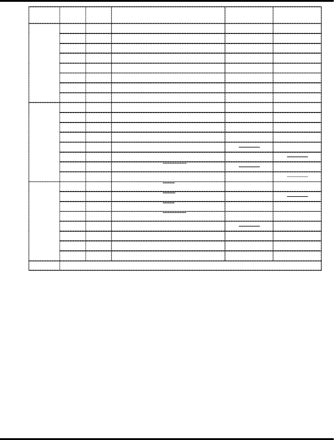
I/O port
address
Data
Bit
IN/OUT Signal Logic “0” Logic “1”
D7 OUT Centronics printer DATA8 0 1
D6 OUT Centronics printer DATA7 0 1
D5 OUT Centronics printer DATA6 0 1
28H
D4 OUT Centronics printer DATA5 0 1
28H
D3 OUT Centronics printer DATA4 0 1
D2 OUT Centronics printer DATA3 0 1
D1 OUT Centronics printer DATA2 0 1
D0 OUT Centronics printer DATA1 0 1
D7 IN 4onSW5 ON OFF
D6 IN 3onSW5 ON OFF
D5 IN 2onSW5 ON OFF
2AH
D4 IN 1onSW5 ON OFF
2AH
D3 IN BUSY signal for TTY BUSY
D2 IN Centronics printer BUSY signal BUSY
D1 IN Centronics printer ERROR signal ERROR
D0 IN Centronics printer PE signal PE
D7 OUT Centronics printer STB signal ON OFF
D6 IN Centronics printer ACK signal ACK
D5 OUT Centronics printer INIT signal OFF ON
2CH
D4 OUT Centronics printer SLCT IN signal OFF ON
2CH
D3 OUT Centronics printer interrupt INT
D2 OUT LED output LD1 ON OFF
D1 OUT LED output LD2 ON OFF
D0 OUT LED output LD3 ON OFF
2EH Mode setting A2H
=REFERENCE=
Logic 0 and 1 indicate logic signal status when the CPU performs signal I/O as data.
8.3 List of Jumper Switch Settings
SERVICE MANUAL
RH5
8.3−21
DA3SEC−85−540−B0
Floppy disk interface(FDC) WD37C65
The WD37C65 is an FDC with built−in VFO capable of supporting up to 4 floppy disk drives and a floppy
disk drive interface driver/receiver.
Software is P PD765A compatible.
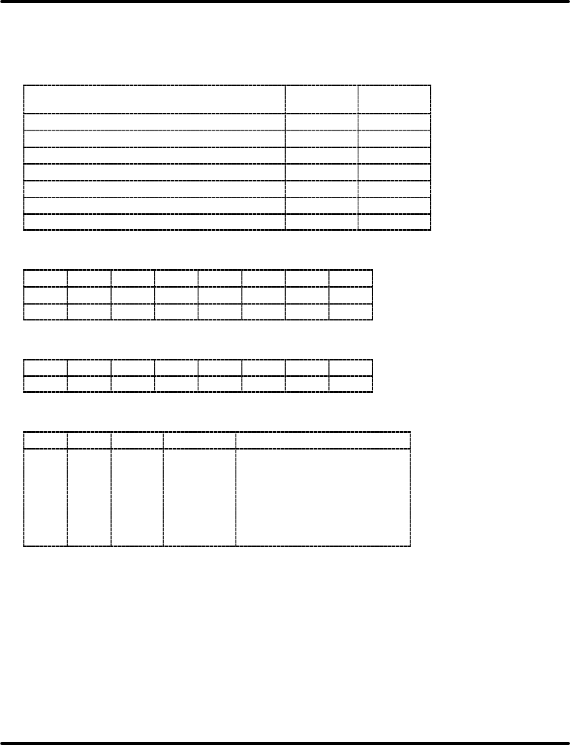
Command
I/O port
address
R/W
Operation resistor (LDOR) 40 W
Control register (LDCR) 42 W
Main status register read 48 R
Data register read 4A R
Data register write 4A W
Switch read 4C R
Control register write 4C W
(1) Operation register
D7
D6 D5 D4 D3 D2 D1 D0
OR7 OR6 OR5 OR4 OR3 OR2 OR1 OR0
(MSEL) (X) MOEN2 MOEN1 DMAEN SRST (X) DSEL
(2) Control register
D7
D6 D5 D4 D3 D2 D1 D0
* * * * * * OR1 OR0
*: Any setting is OK
CR1
CR0 Drive Baud rate Content
0
0
0
0
1
1
1
0
0
1
1
0
0
1
x
x
0
1
x
x
x
500 K
250 K
250 K
300 K
250 K
125 K
125 K
MFM
FM
MFM
MFM
MFM, RST (Factory setting)
FM, RST (Factory setting)
FM
RH5
8.3 List of Jumper Switch Settings
SERVICE MANUAL
8.3−22
DA3SEC−85−540−B0
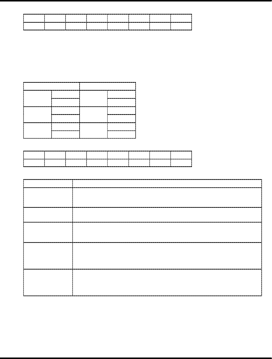
(3) Switch read
D7
D6 D5 D4 D3 D2 D1 D0
S3 S2 S1 RDY 1 1 1 1
RDY
RDY is used to check the FDD unit state by indicating external line (READY) state.
READY = “H” o RDY = “0”
READY = “L” o RDY = “1”
S1−S3
S1−S3 indicate the state at JP17 1 to 3.
JP17
S
1
OPEN
S1
1
1
SHORT
S1
0
2
OPEN
S2
1
2
SHORT
S2
0
3
OPEN
S2
1
3
SHORT
S2
0
(4) Control register
D7
D6 D5 D4 D3 D2 D1 D0
RST * * DMAE MON TMSK * TTRG
Signal Content
RST
(RESET)
Used to initialize the FDC by being changed into an input signal at the RST terminal
on the FDC (WD37C65). It can be used when the transmission is out of sequence.
This signal can be operated under POWER−ON− RESET (and SW) and also OR.
DMAE
(DMA ENABLE)
Enables the DACK signal sent from the DMA channel to transmit data. Turn ON only
when using the DMA and OFF when not.
MON
(MOTOR ON)
Controls the drive motor for the FDD unit. Operated MOTOR ON to use this signal.
MON = “0” o MOTOR ON “H”
MON = “1” o MOTOR ON “L”
TMSK
(TIMER
INTERRUPT
MASK)
This is an interrupt mask bit to mask the timer interruption of FDC (hung−up timer).
Setting this bit 0 will mask the timer interruption. Immediately after power ON, set it
to “0”. Then also set to “0” when not using the timer.
TTRG
(TIMER TRIGGER)
Triggers the hung−up timer (one−shot, triggered to approx. 100 msec).
It is used to trigger the timer for FDD motor ON/OFF controlling.
Setting both TMSK and TIRG to 0 bit will lead to the interruption approx. 100 sec
later. The timer can be re−triggered within 100 msec after the timer was triggered.