Q170226E01.pdf - 第167页
0.5 − 0.7 mm Moving blade Fixed blade B Fixed blade Fixed blade Moving blade A (reference foot) Moving blade A (outer foot) Moving blade B (center foot) Lever spring for cut clinch RH5 5.20 Anvil Lower Clinch Stroke Chec…
Parts
PCB
Gap gauge
(Over 0.5 mm)
Pusher
Pusher rod
Top nut
(M8)
Cam follower
holder (B)
Bottom nut
(M6)
5.20 Anvil Lower Clinch Stroke Check and Adjustment
SERVICE MANUAL
RH5
5.20−1
DA3SEC−83−9C0−A0
5.20 Anvil Lower Clinch Stroke Check and Adjustment
DA3SEC−83−9C0−A0
Sentence No.
When to perform
x When leads of inserted parts are overly
or insufficiently clinched.
Required tools
x Allen wrench
x Slotted screwdriver
Clinching check
1. Set the machine to the auto mode and
insert some parts checking clinching is
performed properly.
Adjusting clinch stroke
1. Set the machine to the auto mode and turn
the hand wheel until the anvil is in the cut
and clinch state.
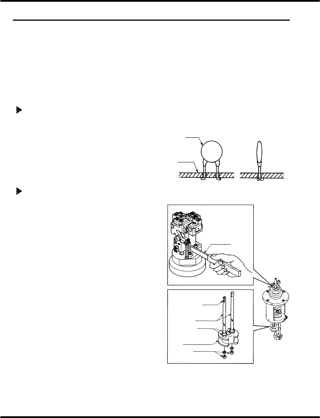
2. Loosen the bottom nut (x 2) of anvil lower
cam follower holder (B). Insert a gap gauge
no smaller than 0.5 mm between the anvil
chuck body and pusher.
=REFERENCE=
In adjusting stroke, leave the gap
gauge in place to prevent the anvil’s
pusher from turning.
0.5 − 0.7 mm
Moving
blade
Fixed
blade B
Fixed
blade
Fixed
blade
Moving blade A
(reference foot)
Moving blade A
(outer foot)
Moving blade B
(center foot)
Lever spring
for cut clinch
RH5
5.20 Anvil Lower Clinch Stroke Check and Adjustment
SERVICE MANUAL
5.20−2
DA3SEC−83−9C0−A0
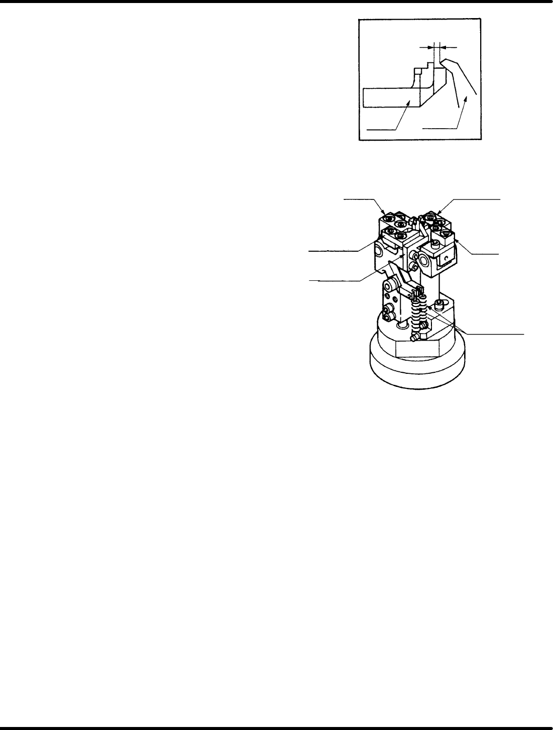
3. Check moving blade B (for center foot) and
the fixed blade overlap one another by 0.5
to 0.7 mm when in the cut and clinch state.
4. If the overlapping distance is outside the
given range, turn the top and bottom nuts of
moving blade A (for outer foot), moving
blade B (for center foot) and the pusher for
adjustment.
=REFERENCE=
Use moving blade B (for center foot) as
a reference when making adjustments.
5. Check overlapping distance of moving blade
A (for reference foot) and the fixed blade in
the same way. If outside of range, turn the
top and bottom nuts of moving blade A (for
outer foot) and the pusher rod for
adjustment.
6. Fix anvil lower cam follower holder B in
place with the top nuts (x 2).
=REFERENCE=
Adjust the stroke of the moving blade A
(for reference foot) the same as that of
the moving blade A (for outer foot).
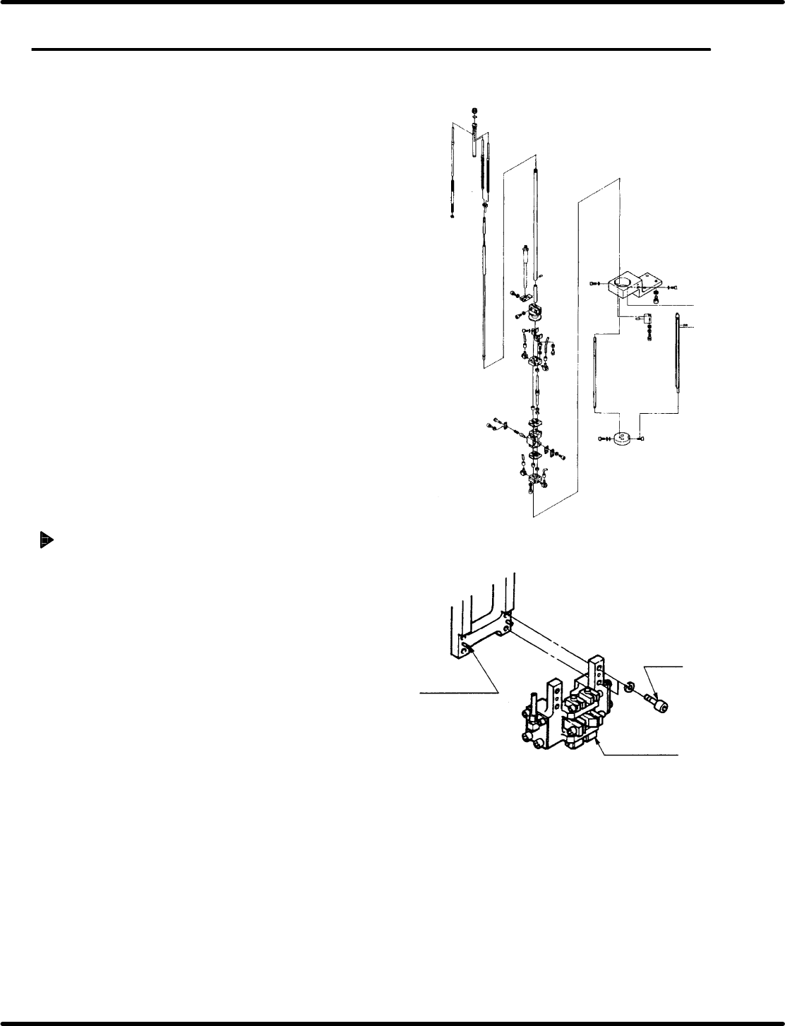
Positioning pin
Bolt A
Guide chuck
5.21 Selector Unit Lead Guide Pin Replacement
SERVICE MANUAL
RH5
5.21−1
DA3SEC−83−9D0−A0
5.21 Selector Unit Lead Guide Pin Replacement
DA3SEC−83−9D0−A0
Sentence No.
When to perform
x When the guide pin does not rise
vertically.
x When the guide pin gets caught on the
insertion hole.
Required tools
x Allen wrench
Guide chuck unit removal
1. Loosen bolt A (x 4) and remove the guide
chuck unit.