Q170226E01.pdf - 第212页
Stopper bracket Air cylinder for cutter Air cylinder for cutter Nut Pusher Cutter cylinder speed controller 5.33 Lead Cutter and T ape Cutter Stroke Adjustment SERVICE MANUAL RH5 5.33−3 DA3SEC−83−9R0−A0 Cylinder drive ad…
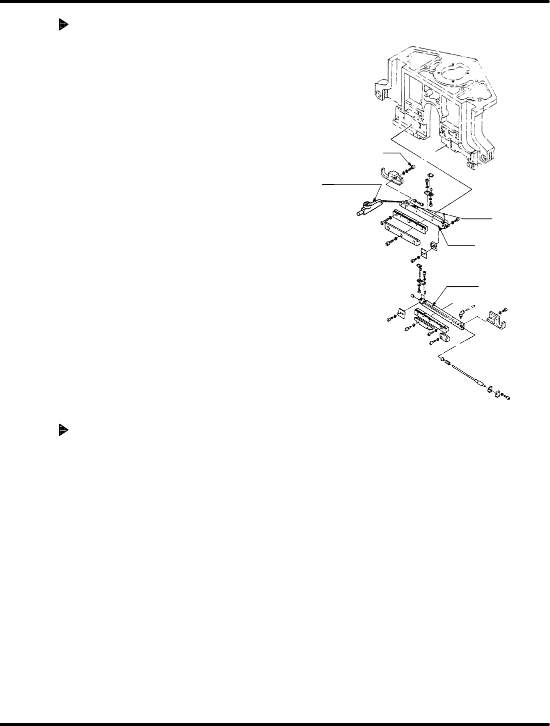
Bolt
Level−operated
dial gauge
Cutter 2
Slider
Cutter 1
A
A
RH5
5.33 Lead Cutter and Tape Cutter Stroke Adjustment
SERVICE MANUAL
5.33−2
DA3SEC−83−9R0−A0
Cam drive (Stroke adjustment of
cutter 2)
1. Disengage the bolt mounting the slide of
the cutter 2.
2. Turn the hand wheel to set the digital
sequence timer to 315q.
3. Squeeze the slider of the cutter 2 so
that the cutter 1 and 2 are lightly
engaged.
(No squeezing)
4. Lock in bolt of the cutter 2 temporality.
5. Set the digital sequence timer to 0q and
set the lever−operated dial gauge to “0”
while pressing it against the slider unit of
the cutter .
6. Disengage the bolt mounting the slider of
the cutter 2 again.
7. Squeeze the slider of the cutter 2 until the
needle of lever−operated dial gauge
indicates 0.1 mm. Then, re−tighten bolts (x
2) to secure the cutter 2.
Cam drive (Cutting check)
1. Perform a trial cutting with an actual
component to make sure that tape
wastes fall off after shaking the
component one or two times.
=CHECK=
If tape waste or lead waste failed to
be cut, check the cutter by referring
to ‘5.15 Lead/Cutter and Tape Cutter
Replacement and Adjustment’.
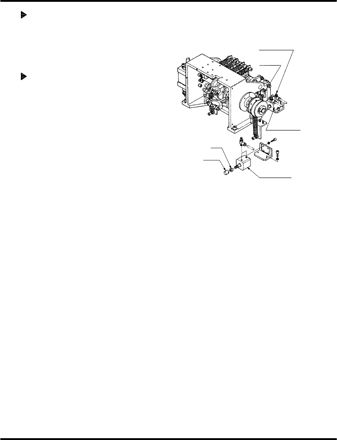
Stopper
bracket
Air cylinder for
cutter
Air cylinder for
cutter
Nut
Pusher
Cutter cylinder
speed controller
5.33 Lead Cutter and Tape Cutter Stroke Adjustment
SERVICE MANUAL
RH5
5.33−3
DA3SEC−83−9R0−A0
Cylinder drive adjustment
1. Set the machine to MANUAL mode
(FEED/MANUAL CUT) and check that the
components are cut as the same
condition described above.
Cylinder drive adjustment (If
components are not cut properly:)
1. Set the digital sequence timer to 315q.
2. Disengage the bush and nut at the end of
the air cylinder for cutter.
=REFERENCE=
It is advisable to remove the stopper
bracket at the cutter reverse limit for
ease of adjustment.
3. Turn ON “CUTTER” on the sub−control
panel.
4. Turn the pusher at the end of the air
cylinder for cutter to insert it into the
cam lever without gap.
5. Turn OFF “CUTTER” on the sub−control
panel.
6. Turn the pusher at the end of the air
cylinder for cutter by 90q (to right) to
secure the pusher and nut in the
direction the pusher stretches.
7. Turn the hand wheel to set the digital
sequence timer to 0q.
8. Set the machine to MANUAL mode
(FEED/MANUAL CUT) and check that
how well the components are cut.
=REFERENCE=
If cutting error occurs only when the
cutter cut electronic components with
few hard lead increase the rate of
the speed controller for cutter
cylinder.

RH5
5.33 Lead Cutter and Tape Cutter Stroke Adjustment
SERVICE MANUAL
5.33−4
DA3SEC−83−9R0−A0
= MEMO =