Q170226E01.pdf - 第41页
RH5 2.1 Insertion Process and Driving Transmission Flow SERVICE MANUAL 2.1−2 DA3SEC−82−120−A0 = MEMO =
2.1 Insertion Process and Driving Transmission Flow
SERVICE MANUAL
RH5
2.1−1
DA3SEC−82−120−A0
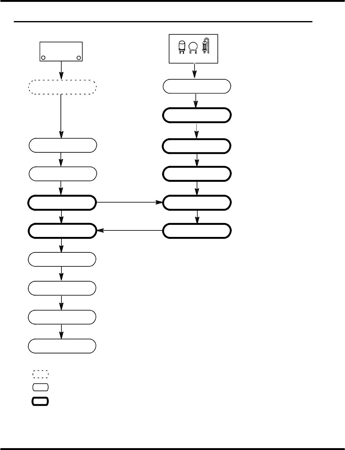
2.1 Insertion Process and Driving Transmission Flow
DA3SEC−82−120−A0
Sentence No.
PC board
PCB feed
PCB transfer
Insertion position
selection
Insertion complete
Loader conveyor
(Machine)
PCB transfer
PCB stock
Unloader conveyor
(Machine)
(Radial component)
Feeder carriage
1 pitch feed
Parts cassette
Transfer chuck
Cutter
Insertion head
Anvil
X−Y table transfer
PCB positioning
Component chucking
Component stock
Lead wire/Base
cutting
Component insertion
Lead wire cut & clinch
PCB positioning release
X−Y table origin return
BHU
=REFERENCE=
Indicates operation with optional device (BHU).
Indicates a machine operation with operating units described at the right.
Indicates a sequence of operation to be repeated for the number of components to be
inserted on a PC board.

RH5
2.1 Insertion Process and Driving Transmission Flow
SERVICE MANUAL
2.1−2
DA3SEC−82−120−A0
= MEMO =
2.2 Electronic Component Insertion and Related Operations
SERVICE MANUAL
RH5
2.2−1
DA3SEC−82−260−A0
2.2 Electronic Component Insertion and Related
Operations
DA3SEC−82−260−A0
Sentence No.
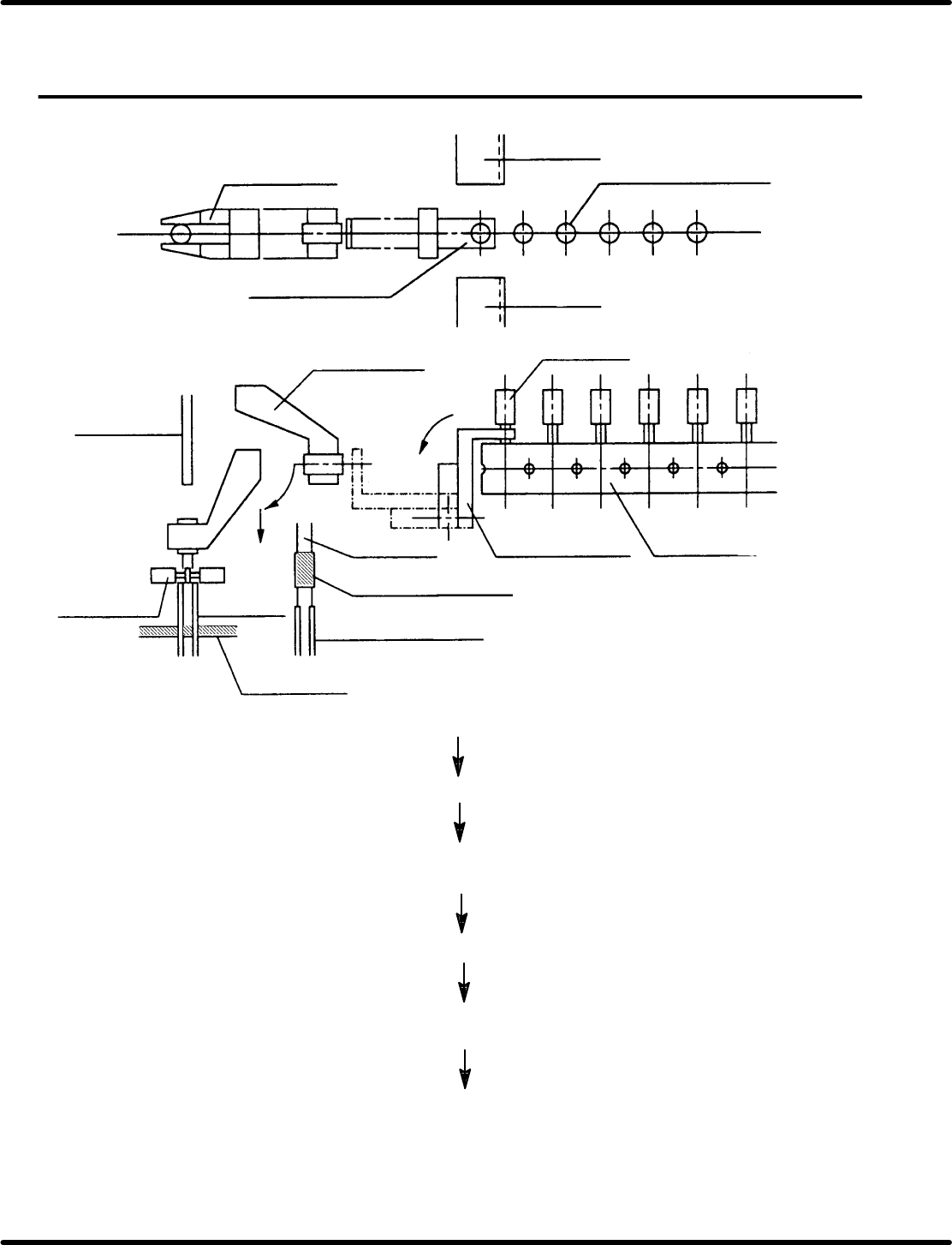
(7) Cutter
(1) Electronic component
(taped)
(2) Transfer chuck
(7) Cutter
(1) Electronic
component
(1) Electronic component
(3) Insertion chuck
(3) Insertion chuck
(4) Pusher
(4) Pusher
Guide chuck
(5) Lead guide pin
(6) PC board
(5) Lead
guide pin
(A)
(B)
(C)
(2) Transfer chuck
(8) Base tape
Electronic component (1) is fed by one pitch and held with transfer
chuck (2).
Leads and base tape (8) are cut by cutter (7).
Transfer chuck (2) rotates in the direction of arrow (A) and the
component is transferred to insertion chuck (3).
Insertion chuck (3) rotates in the direction of arrow (B) and lowers
in the direction of arrow (C).
Electronic component (1) is held by pusher (4) and lead guide pin
(5), and is inserted into holes in PC board (6).
Component leads are cut and clinched so that the component is
fixed on PC board (6).