Q170226E01.pdf - 第129页
RH5 5.9 Insertion Head Insertion Chuck 90 q Swing Check and Adjustment SERVICE MANUAL 5.9−2 DA3SEC−83−8RO−A0 Adjusting swing 1. Disengage the upper and lower stoppers. 2. Disengage the nut of the connecting rod and adjus…
5.9 Insertion Head Insertion Chuck 90q Swing Check and Adjustment
SERVICE MANUAL
RH5
5.9−1
DA3SEC−83−8RO−A0
5.9 Insertion Head Insertion Chuck 90G Swing Check
and Adjustment
DA3SEC−83−8RO−A0
Sentence No.
When to perform
x When cut parts arrive slanted at the
transfer chuck.
x When parts from the transfer chuck
arrive slanted at the insertion chuck.
x When insertion errors occur
frequently.
x Allen wrench
x Box wrench
x Lever−operated dial gauge
Required tools
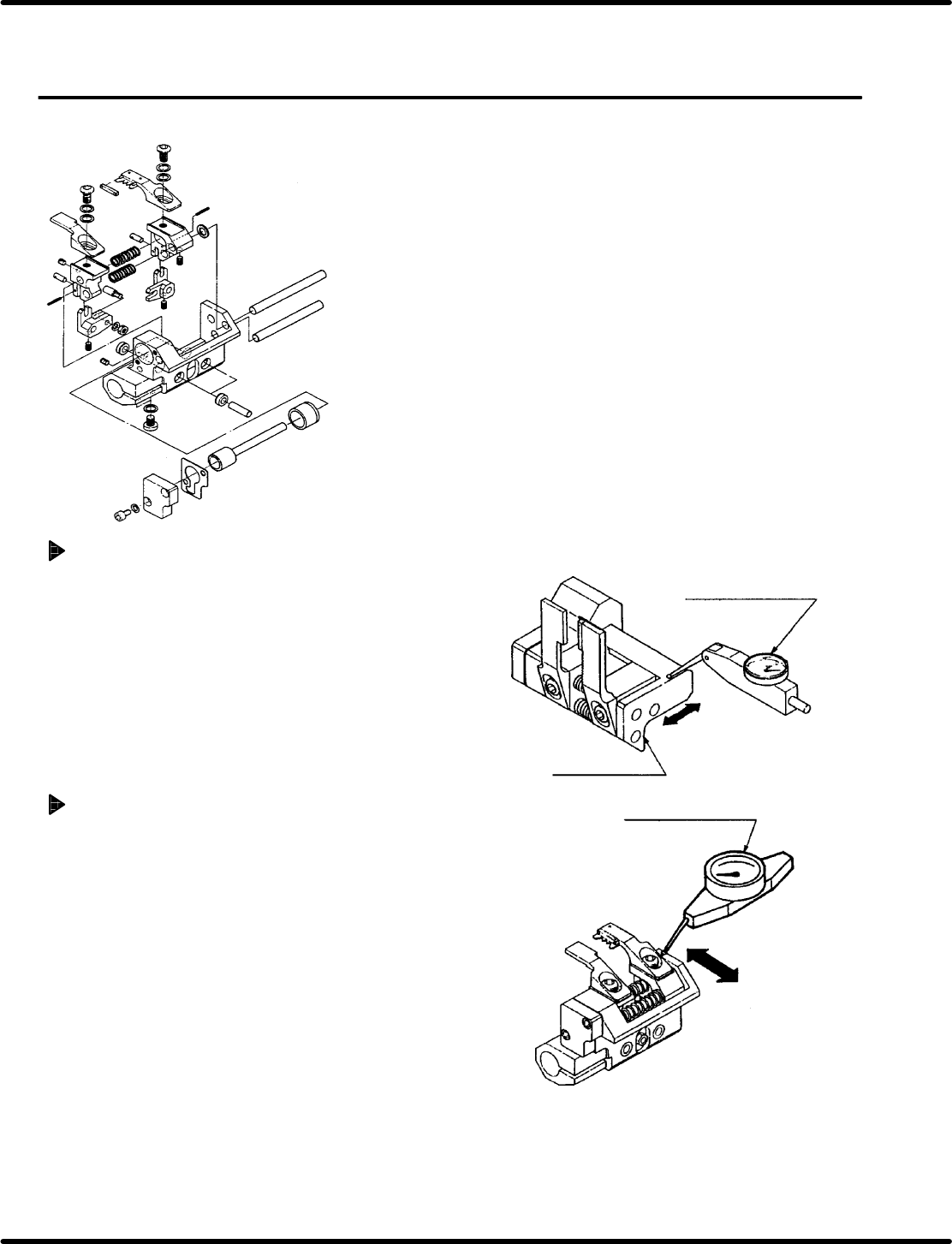
90G swing check (At parts handover)
1. Turn the hand wheel until reaching the 90q
position on the digital sequence timer.
2. Attach the lever−operated dial gauge to the guide
rail (fixed side) on the X−Y table.
3. Set the measuring needle on the top surface of
the transfer chuck.
4. Move the X−Y table in the Y direction by hand
checking transfer chuck parallelism against the
guide rail is within 0.05/15 − 20 mm.
0G swing check (During cutting)
1. Turn the hand wheel again until reaching the 0q
position on the digital sequence timer.
2. Set the measuring needle on the rear surface of
the transfer chuck.
3. Move the X−Y table in the Y direction by hand
checking transfer chuck parallelism against the
guide rail is within 0.5/15 − 20 mm.
Lever−operated dial gauge
Y direction
Transfer chuck
Y direction
Lever−operated dial
gauge
Parallelism:
0.05/15 − 20 mm
Parallelism:
0.05/15 − 20 mm
RH5
5.9 Insertion Head Insertion Chuck 90q Swing Check and Adjustment
SERVICE MANUAL
5.9−2
DA3SEC−83−8RO−A0
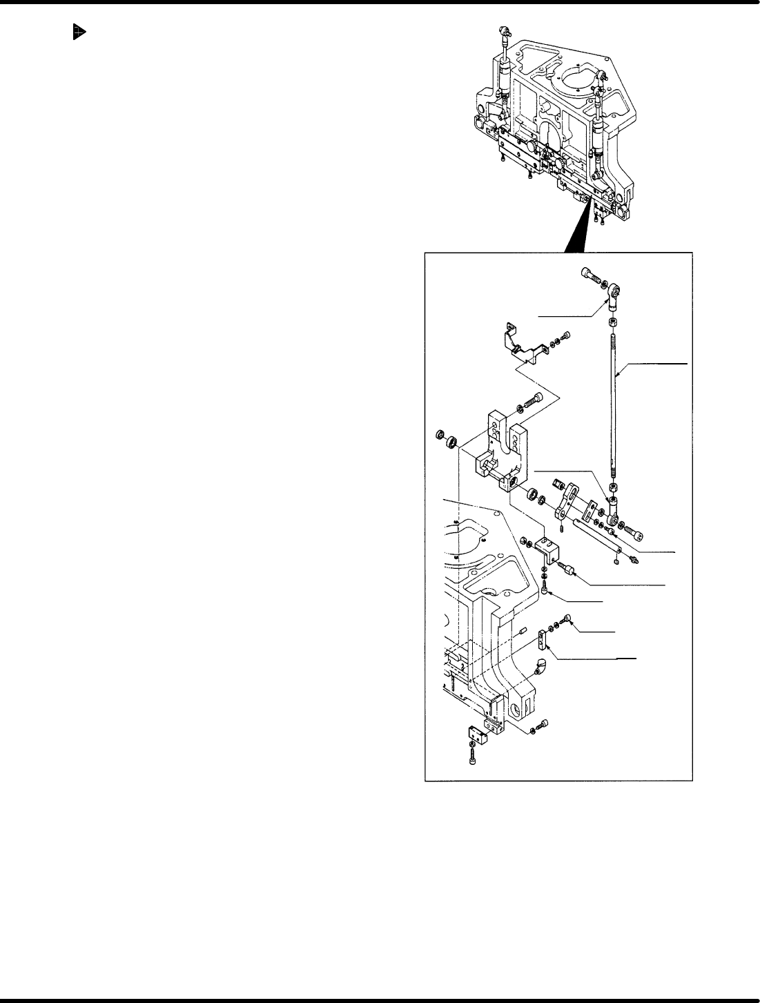
Adjusting swing
1. Disengage the upper and lower
stoppers.
2. Disengage the nut of the connecting
rod and adjust the connecting rod to
obtain the 0 q swing accuracy. Then
retighten the nut of the connecting rod.
3. Set the digital sequence timer to 90q to
measure the 90 q swing accuracy.
4. If the 90 q swing accuracy cannot be
obtained, loosen the bolt A and move
the rod end B to change lever ratio.
5. Repeat steps 2 through 4 until 0q and
90q swings are obtained.
=CHECK=
The parallelism shall be with in 0.05
mm at the 0q and 90q positions.
6. Secure the bolts C (x 2) of the upper
stopper at 0q position on the digital
sequence timer.
7. Secure the bolts B (x 2) of the lower
stopper at 90q position on the digital
sequence timer.
8. Check that the swings both 0q and 90q
are obtained again.
Rod end A
Connecting
rod
Rod end B
Bolt A
Stopper (lower)
Stopper (upper)
Bolt C
Bolt (B)
5.10 Insertion Head Transfer Chuck Claw/Rubber Replacement/Adjustment
SERVICE MANUAL
RH5
5.10−1
DA3SEC−83−8SO−A0
5.10 Insertion Head Transfer Chuck Claw/Rubber
Replacement/Adjustment
DA3SEC−83−8SO−A0
Sentence No.
When to perform
x When inserted parts are often
slanted.
x When insertion errors occur
frequently.
x Allen wrench
Required tools
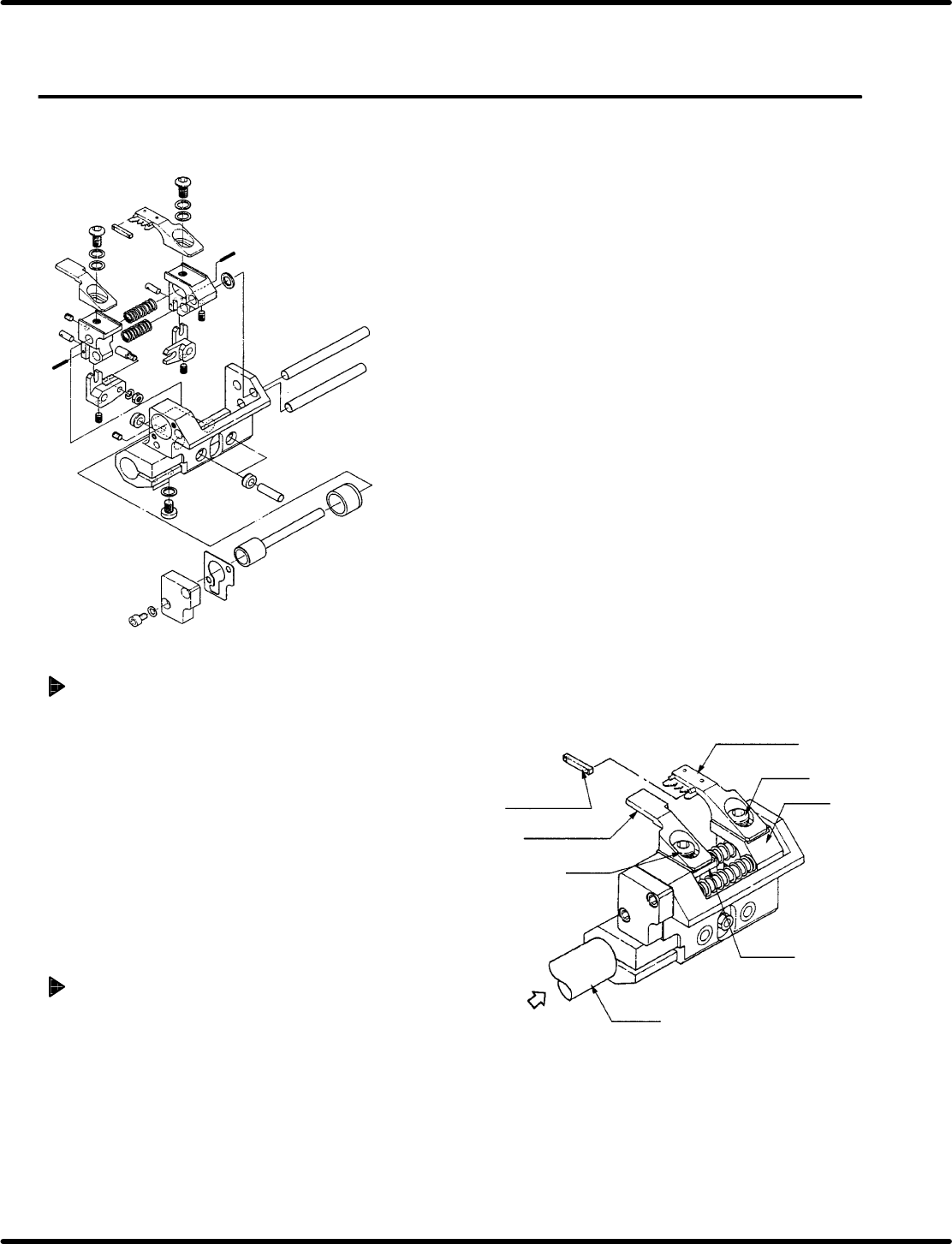
Chuck claw replacement
1. Remove bolts A (x 1) and B (x 1) fixing
chuck claws A and B in place.
2. While holding down the new claws against
the levers, fix them in place with bolts A (x 2)
and B (x 2).
=CHECK=
x Check the claws do not contact parts
when closed.
x Check the claws do not contact parts
when the transfer chuck turns 100q.
Chuck rubber replacement
1. Remove the rubber from the chuck claws.
=REFERENCE=
The rubber pops out easily.
2. Attach a new rubber.
Chuck rubber
Chuck claw B
Bolt B
Lever B
Lever A
Chuck claw B
Bolt B
Rotation
axis
Air