Q170226E01.pdf - 第311页
RH5 8.3 List of Jumper Switch Settings SERVICE MANUAL 8.3−14 DA3SEC−85−540−B0 DIP switch settings (1) SW1: multibus interrupt level setting Bit 7 Bit 6 Bit 5 Bit 4 Bit 3 Bit 2 Bit 1 Bit 0 Interrupt level OFF OFF OFF OFF …
8.3 List of Jumper Switch Settings
SERVICE MANUAL
RH5
8.3−13
DA3SEC−85−540−B0
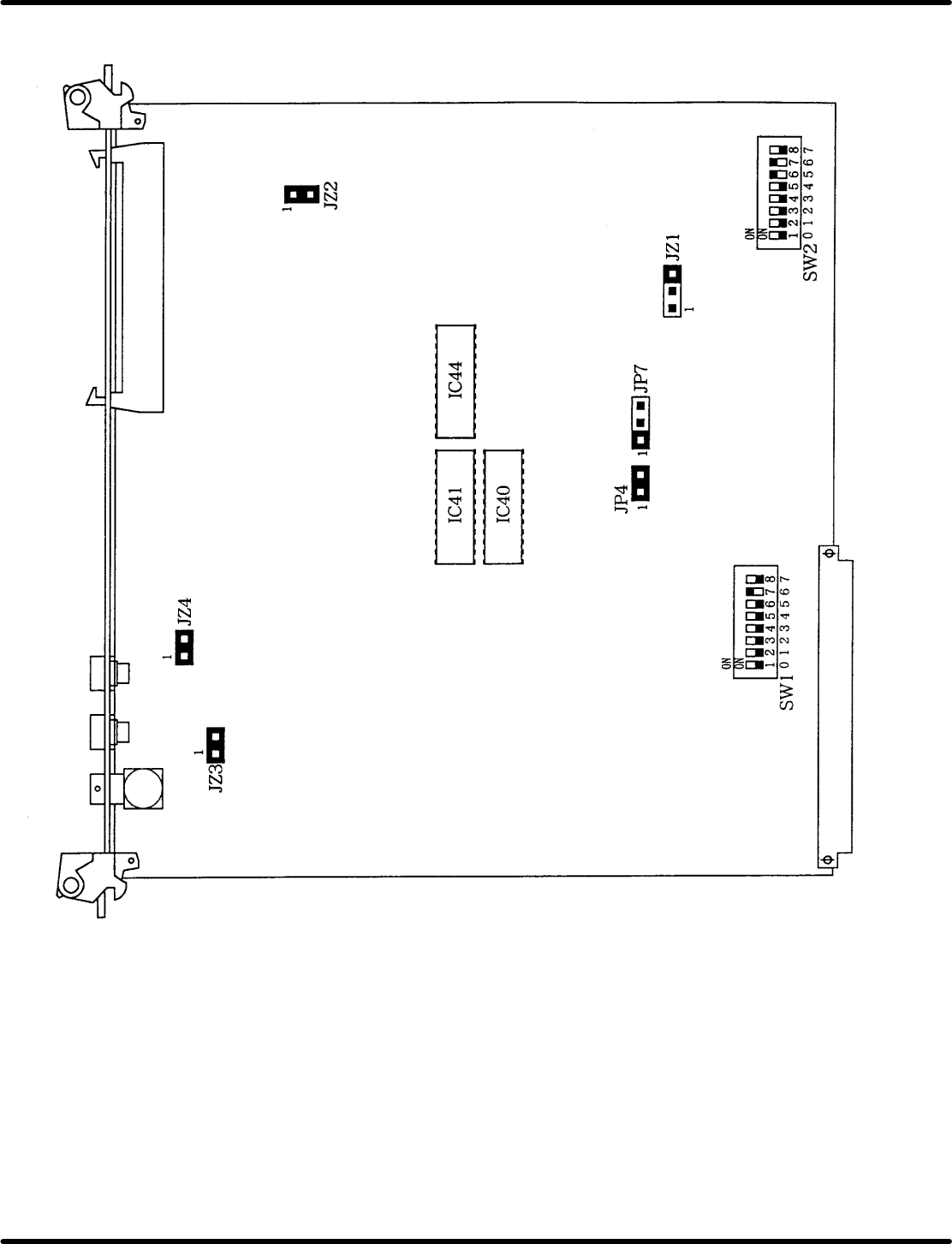
8.3.3 RCG (I) Board Setting (X984 − 211)
RH5
8.3 List of Jumper Switch Settings
SERVICE MANUAL
8.3−14
DA3SEC−85−540−B0
DIP switch settings
(1) SW1: multibus interrupt level setting
Bit 7
Bit 6 Bit 5 Bit 4 Bit 3 Bit 2 Bit 1 Bit 0
Interrupt
level
OFF
OFF
OFF
OFF
OFF
OFF
OFF
ON
OFF
OFF
OFF
OFF
OFF
OFF
ON
OFF
OFF
OFF
OFF
OFF
OFF
ON
OFF
OFF
OFF
OFF
OFF
OFF
ON
OFF
OFF
OFF
OFF
OFF
OFF
ON
OFF
OFF
OFF
OFF
OFF
OFF
ON
OFF
OFF
OFF
OFF
OFF
OFF
ON
OFF
OFF
OFF
OFF
OFF
OFF
ON
OFF
OFF
OFF
OFF
OFF
OFF
OFF
INT0
INT1
INT2
INT3
INT4
INT5
INT6
INT7
=REFERENCE=
SW1 factory setting: INT6
SW2 (operation mode [Compatible ROM version] setting)
Bit 5 Bit 6 Bit 7 Operation mode
OFF
ON
OFF
ON
OFF
OFF
ON
ON
OFF
OFF
OFF
OFF
Version: under 1.14
Version: 1.14T2
Version: 1.15
Version: over 1.16
=REFERENCE=
x Bit 0 − 4: Not used
x Factory setting: Bit 5 and 6 are ON. Others are OFF.
8.3 List of Jumper Switch Settings
SERVICE MANUAL
RH5
8.3−15
DA3SEC−85−540−B0
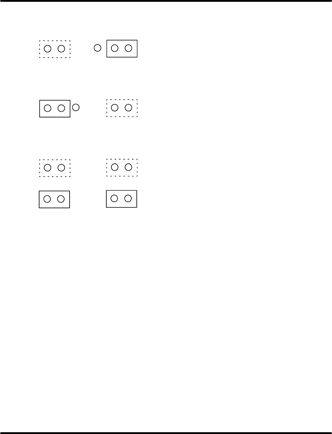
Jumper switch settings
(1) JP4, JP7 (Fixed)
JP4
JP7
1
1
(2) JZ1, JZ2 (Fixed)
JZ4
JZ2
1
1
(3) Camera cable (Fixed)
JZ3
JZ4
1
1
When Straight cable is used.
When L type cable is used.
=REFERENCE=
x Factory setting is for Straight cable