Q170226E01.pdf - 第51页
RH5 2.4 Control Configuration SERVICE MANUAL 2.4−2 DA3SEC−82−130−B0 No. Part Name 1 CNC−4S (I) card 2 CPU−286E (I)−12 card 3 RCG (I) card 4 MIO E (I) card 5 SEQ−SE (I) card
2.4 Control Configuration
SERVICE MANUAL
RH5
2.4−1
DA3SEC−82−130−B0
2.4 Control Configuration
DA3SEC−82−130−B0
Sentence No.
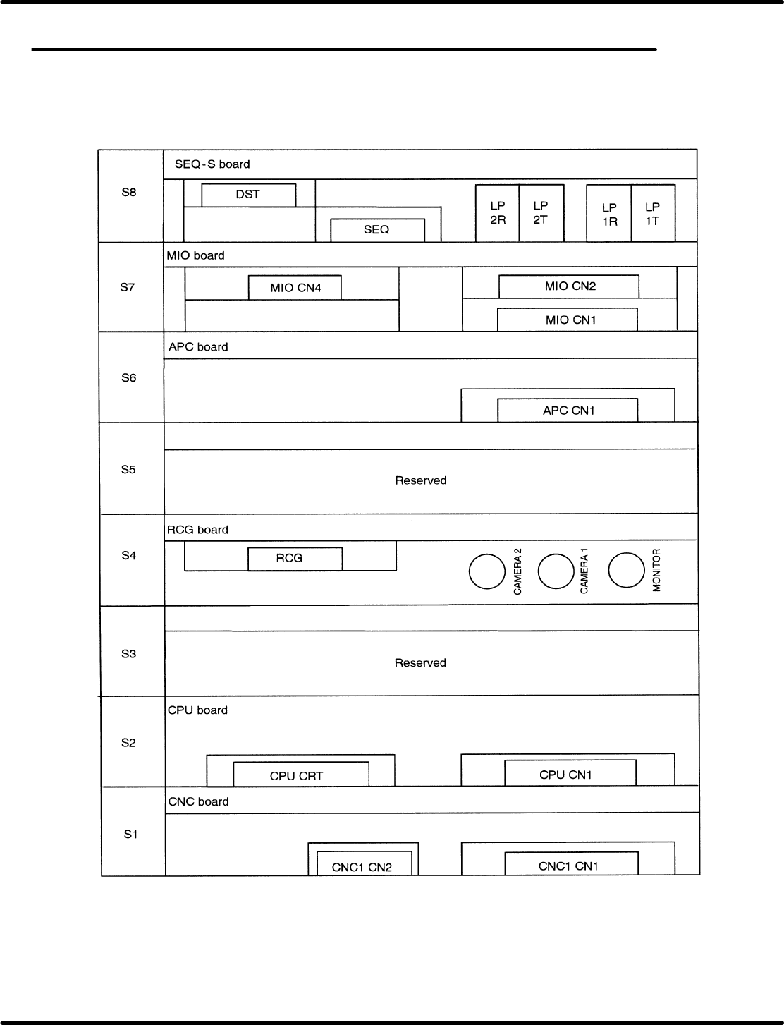
2.4.1 Panadac−791 Board Configuration
Use and connector arrangement of respective boards are as follows:
=REFERENCE=
Arrangements of S2 through S8 can be changed.

RH5
2.4 Control Configuration
SERVICE MANUAL
2.4−2
DA3SEC−82−130−B0
No. Part Name
1 CNC−4S (I) card
2 CPU−286E (I)−12 card
3 RCG (I) card
4 MIO E (I) card
5 SEQ−SE (I) card
2.4 Control Configuration
SERVICE MANUAL
RH5
2.4−3
DA3SEC−82−130−B0
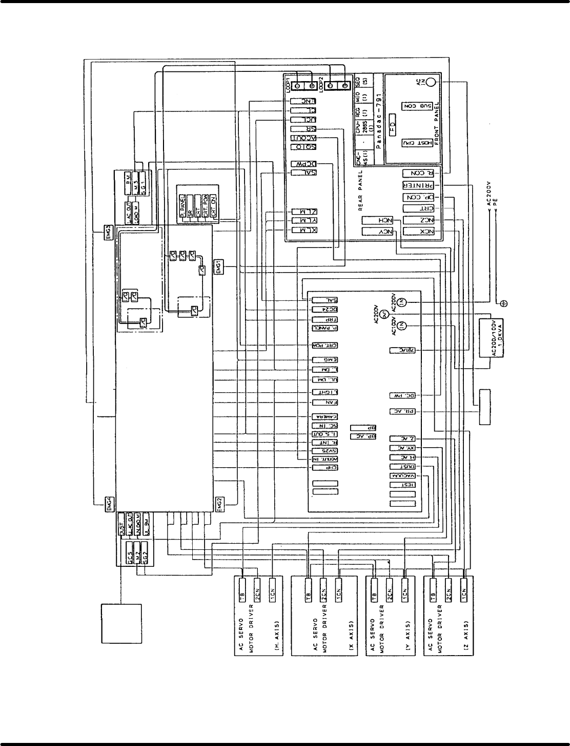
2.4.2 Control System Diagrams
Tape cut
waste
bottle unit
Option UL side
Z motor
Z encoder
X motor
X encoder
Y motor
Y encoder
Hmotor
H encoder
Distortion gauge
Forced−oil value
Interlock key SW
Interlock SW
Recognition light
Fan motor
Handy lamp
Unloader motor
Loader motor
XYZ−axes safety limit SW
Option
Optical module
(Upper base unit)
Option L side
Cam encoder
Main control panel
Power source unit
Down
transfer
Printer
Factory power source
V acuum
Power source unit
RH5
RH5
Reserved
Reserved
Reserved
Reserved