Q170226E01.pdf - 第174页
Guide pun B Guide pun A Anvil Bolt Lever− operated dial gauge Parallelism: 0.02 mm 5.23 Selector Unit Guide Pin Parallelism Check and Adjustment SERVICE MANUAL RH5 5.23−1 DA3SEC−83−9F0−A0 5.23 Selector Unit Guide Pin Par…
Selector rod
Selector rod
Guide pin rod
Selector
rod
Plate A
Bolt A
Bolt A
Plate A
Connecting
block
Connect−
ing block
RH5
5.22 Selector Unit Selector Rod Replacement
SERVICE MANUAL
5.22−2
DA3SEC−83−9E0−A0
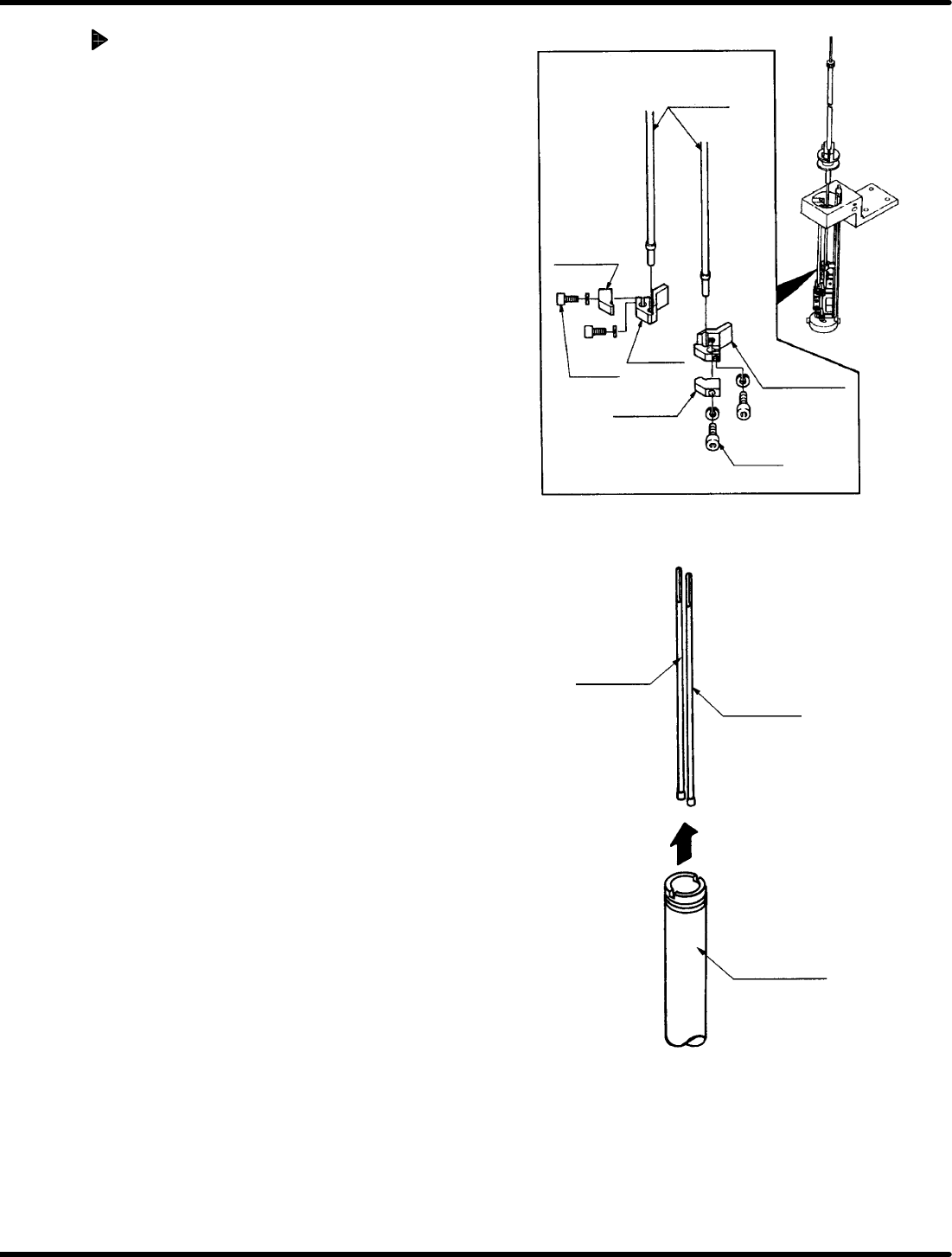
Selector rod replacement
1. Turn power OFF and remove the guide
chuck, anvil and guide pin.
=REMARKS=
Refer to ‘5.21 Selector Unit Lead Guide
Pin Replacement’.
2. Bring the rod to the 200q position on the
digital sequence timer.
3. Remove the bolt A and plate A.
4. Remove the selector rod.
5. Pull the selector rods upwards out of the
guide pin rod.
6. nsert new selector rods following the
removal procedure in reveres.
7. Tighten bolt A.
8. After installing the rods, turn the hand wheel
checking the guide pin moves vertically
without getting caught.
=REFERENCE=
x Press each pitch changeover switch
(2.5/5.0/5.0ALL) on the sub−control panel
to check that the appropriate rod is
selected. (Check that the current angle
indicates 230q )
Guide pun B
Guide pun A
Anvil
Bolt
Lever−
operated dial gauge
Parallelism: 0.02
mm
5.23 Selector Unit Guide Pin Parallelism Check and Adjustment
SERVICE MANUAL
RH5
5.23−1
DA3SEC−83−9F0−A0
5.23 Selector Unit Guide Pin Parallelism Check and
Adjustment
DA3SEC−83−9F0−A0
Sentence No.
When to perform
x When the guide pin does not rise
vertically.
x When the guide pin gets caught on the
insertion hole.
Required tools
x Lever−operated dial gauge
x Allen wrench
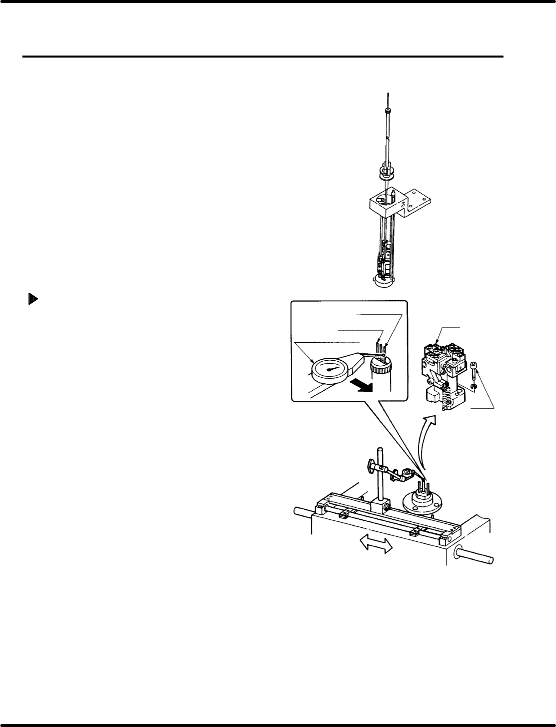
Measuring parallelism
1. Turn ON power to the machine. Loosen the
bolt (x 2) and remove the anvil.
2. In manual mode, turn the hand wheel until the
cam shaft is at approximately the 210q position
on the digital sequence timer .
3. Attach the lever−operated dial gauge to the
guide rail (fixed side) on the X− Y table.
4. Set the measuring needle on the side
surface of the guide pin A and bring the
scale reading to “0” (reference point).
=CHECK=
x Do not apply excessive force on the
guide pin shaft when contacting it with
the measuring needle.
x Bring the scale reading to “0”
(reference point ) at a point on the side
surface of the guide pin where the
maximum reading is produced.
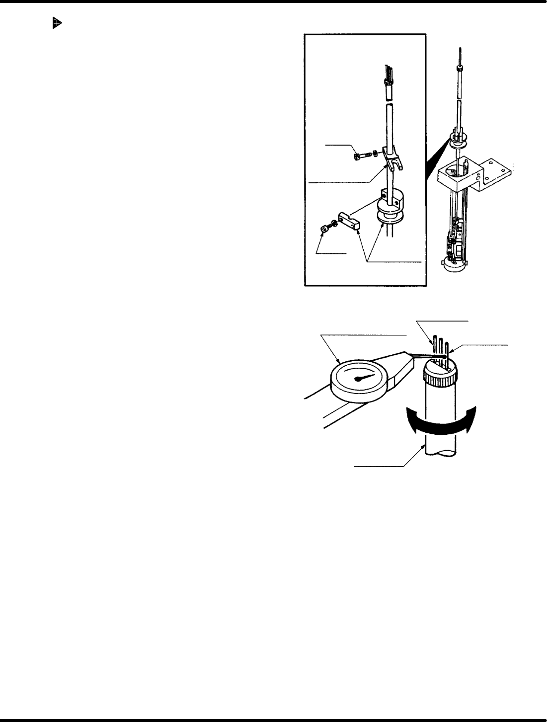
5. Move the X−Y table in the x direction by
hand. Set measuring needle on the side
surface of guide pin B and check parallelism
is no more than 0.02 mm.
=CHECK=
If sliding the X−Y table by hand, make
sure the table does not slip in the Y
direction.
Bolt A
Positioning block
Bolt B
cam follower
holder
Lever−operated dial
gauge
Guide pin A
Guide pin B
Guide pin rod
RH5
5.23 Selector Unit Guide Pin Parallelism Check and Adjustment
SERVICE MANUAL
5.23−2
DA3SEC−83−9F0−A0
Adjusting parallelism
1. Turn the hand wheel to set the digital
sequence timer to 210q.
2. Loosen the bolt (x 1) of the guide pin
upper/lower stopper.
3. Loosen the bolt A (x 1) of the positioning
block.
4. Turn the cam follower holder to obtain the
parallelism.
5. After the parallelism is obtained, retighten
the bolt A (x 1) of the positioning block.
6. Retighten the bolt (x 1) of the guide pin
upper/lower stopper.
=CHECK=
Parallelism may vary depending on
how the bolts are tightened. So be sure
to set the measuring needle on the side
face of the lever−operated dial gauge
when tightening the bolts.