Q170226E01.pdf - 第351页
RH5 8.4 AC Servomotor Drivers SERVICE MANUAL 8.4−14 DA3SEC−85−480−A0 LED Indication for T roubleshooting 7−seg ment LED indication Digital Operator Indication (T raceback Monitor) Lighting Condition Probable Causes Count…
8.4 AC Servomotor Drivers
SERVICE MANUAL
RH5
8.4−13
DA3SEC−85−480−A0
Digital Operator and 7−segment LED Indication for Troubleshooting
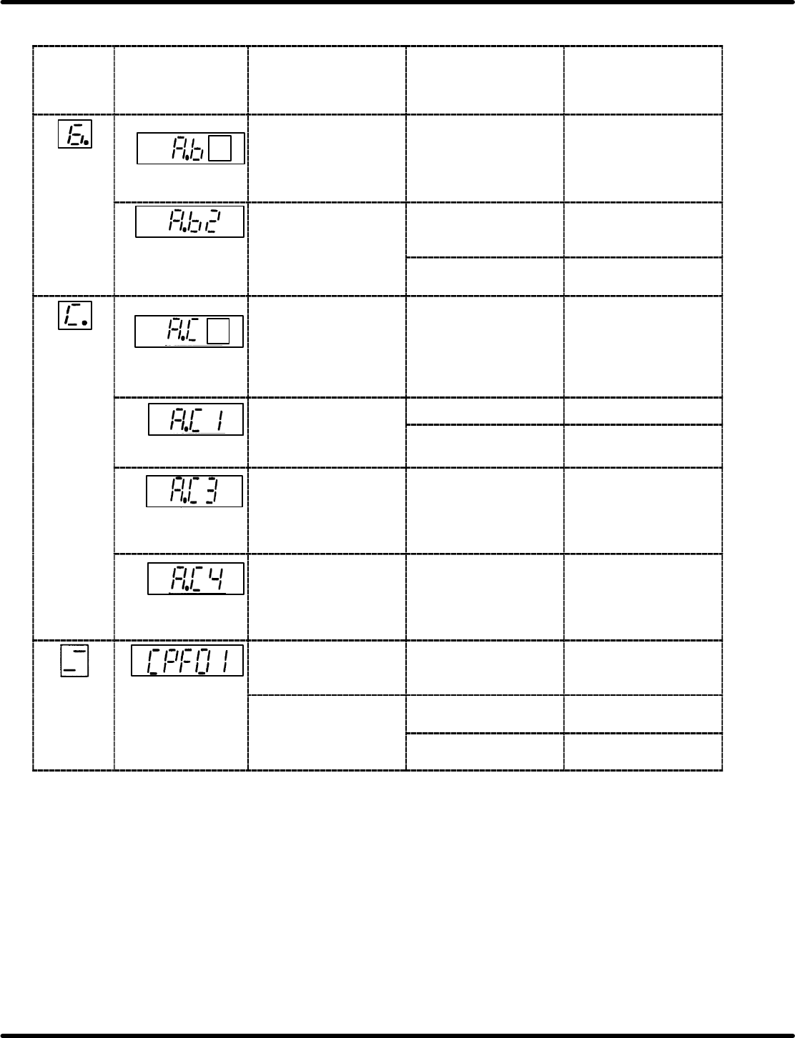
7−seg ment
LED
indication
Digital Operator
Indication
(T raceback
Monitor)
Lighting Condition Probable Causes Countermeasures
=NOTE= 1
AD error
Lights up when power
to the control circuit is
supplied.
Defective control
circuit board (1PWB)
Replace the
SERVOPACK.
Lights up during
operation.
Erroneous operation
with the reference
input reader
Press <RESET> key
and resume operation.
Failure of the
reference input reader
Replace the
SERVOPACK.
=NOTE= 1
Overrun
prevention
Lights up when power
to the control circuit is
supplied.
Defective control
circuit board (1PWB)
Replace the
SERVOPACK.
The motor starts
momentarily
then
LED
Motor connection error Correct the wiring.
Overrun
momen
t
ar
il
y
th
en
LED
comes ON.
Optical encoder
connection error
Correct wiring of the
optical encoder.
Wire break with
phase PA, PB
The motor starts
momentarily then LED
comes ON.
Wire break with phase
PA, PB of the optical
encoder
Correct signal cables
of the optical encoder.
Wire break with
phase PC
The motor starts
momentarily then LED
comes ON.
Wire break with phase
PC of the optical
encoder
Correct wiring of the
optical encoder.
CPU
fault
Lights up when power
to the control circuit is
supplied.
Defective control
circuit board (1PWB)
Replace the
SERVOPACK.
CPU fault
Lights up during
operation.
Malfunction of internal
circuit
Press <RESET> key
and resume operation.
p
Failure of internal
circuit
Replace the
SERVOPACK.
=NOTE=
1. j means an unspecified number.
RH5
8.4 AC Servomotor Drivers
SERVICE MANUAL
8.4−14
DA3SEC−85−480−A0
LED Indication for Troubleshooting
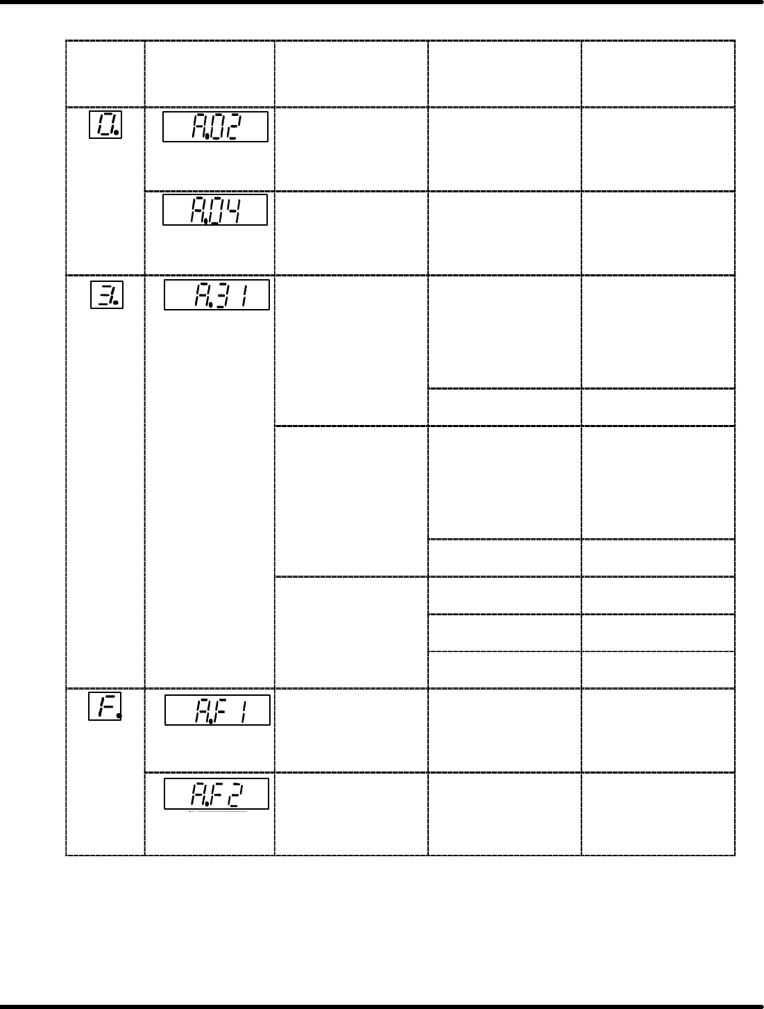
7−seg ment
LED
indication
Digital Operator
Indication
(T raceback
Monitor)
Lighting Condition Probable Causes Countermeasures
Parameter
breakdown
Lights up when power
to the control circuit is
supplied.
Defective control
circuit board (1PWB)
Replace the
SERVOPACK.
Parameter setting
error
Lights up during
parameter change.
The value outside the
setting range by serial
communi− cations was
set.
Reset the value.
Overflow (Too
much position
deviation)
Although reference
pulse is input, PG
pulse does not return.
x Motor connection
error
x Optical encoder
connection error
x Correct the wiring.
x Check pulses in
phases A, B and C on
2CN and correct
wiring.
(disconnection, short
circuit)
Defective control
circuit board (1PWB)
Replace the
SERVOPACK.
The motor runs fast
and overflow occurs.
x Motor connection
error
x Optical encoder
connection error
x Correct the wiring.
x Check pulses in
phases A, B and C on
2CN and correct
wiring.
(disconnection, short
circuit)
Defective control
circuit board (1PWB)
Replace the
SERVOPACK.
Although the
movement is normal,
ii
l
f
Improper SERVO−
PACK adjustment
Increase the speed
loop gain.
giving a long reference
causes overflow.
Too much load
capacity
Check for overload or
load inertia.
Too high reference
pulse frequency
Slow up/down the
reference pulse.
Power cable
open−phase
Lights up when power
to the main circuit is
supplied.
Open−phase in power
supply
Check the main circuit
power.
Power supply
startup error
Lights up when power
to the main circuit is
supplied.
Power supply
distortion is large.
Check the main circuit
power.

8.5 Cycle Timer Setting
SERVICE MANUAL
RH5
8.5−1
DA3SEC−85−490−B0
8.5 Cycle Timer Setting
DA3SEC−85−490−B0
Sentence No.
CS
Ad-
dress
Name Angle Description
1
00
01
XY Hold
M: 130q
LL:
140
ON timing X/Y axis emergency stop timing
1
00
01
XY
−
H
o
ld
LL
:
140
−342q
OFF timing X/Y axis start timing
2
00
01
Spare
ON timing
2
00
01
S
pare
OFF timing
3
00
02
Z axis
hold
condition
185
ON timing Z axis emergency stop timing
3
00
02
Z
−ax
i
s
h
o
ld
con
diti
on
185
−(340q)
OFF timing Z axis start condition
4
00
03
Middle
1
15 155
q
ON timing H axis acceleration effective start
timing
4
00
03
Middle
re−acceleration
1
15
−
155
q
OFF timing H axis acceleration effective stop
timing
5
00
04
T
est
ON timing
5
00
04
T
es
t
OFF timing
6
00
05
Cut waste drop high
275 290
q
ON timing Cut waste drop valve ON timing
0.36/0.29 (sec)
6
00
05
Cut
waste
drop
high
speed
275
−
290
q
OFF timing Cut waste drop valve OFF timing
0.36/0.29 (sec)
7
00
06
Cutter
return
220 310
q
ON timing Used for software debugging (Usually
not used)
7
00
06
C
u
tt
er re
t
urn
220
−
310
q
OFF timing Used for software debugging (Usually
not used)
8
00
07
Cut waste drop low
285 300
q
ON timing Cut waste drop valve ON timing
0.45/0.6 (sec)
8
00
07
Cut
waste
drop
low
speed
285
−
300
q
OFF timing Cut waste drop valve OFF timing
0.45/0.6 (sec)
9
00
10
Origin
358 10
q
ON timing H axis origin ON timing
9
00
10
O
r
i
g
i
n
358
−
10
q
OFF timing H axis origin OFF timing
10
00
1
1
Origin
stop
low
speed
325 10
q
ON timing 0.45/0.6 sec H axis origin stop timing
10
00
1
1
O
r
i
g
i
ns
t
op
l
o
w
spee
d
325
−
10
q
OFF timing −
1
1
00
12
Origin stop medium
310 10
q
ON timing 0.36 sec H axis origin stop timing
1
1
00
12
Origin
stop
medium
speed
310
−
10
q
OFF timing −
12
00
13
Origin stop high
310 10
q
ON timing 0.29 sec H axis origin stop timing
12
00
13
Origin
stop
high
speed
310
−
10
q
OFF timing −
13
00
14
Special stop + guide
290 320
q
ON timing Not used
13
00
14
Special
stop
+
guide
pin change
290
−
320
q
OFF timing Insertion pitch changeover timing
ON timing Inching 1 stop timing
14 00 15 Inching stop 70−230q
OFF timing Inching 2 stop timing
(Only 0.45/0.6sed)
15
00
16
Middle stop + part
190 320
q
ON timing Part exhaust check timing
15
00
16
Middle
stop
+
part
exhaust
190
−
320
q
OFF timing X/Y/Z axis action error stop timing