Q170226E01.pdf - 第281页
RH5 7.3 Digital Operator SERVICE MANUAL 7.3−4 DA3SEC−84−310−A0 Display Procedure Remarks 7 Repeat steps 5 and 6 as necessary . 8 Press DA T A key to store data and then press DOWN key to change the setting value at the r…
7.3 Digital Operator
SERVICE MANUAL
RH5
7.3−3
DA3SEC−84−310−A0
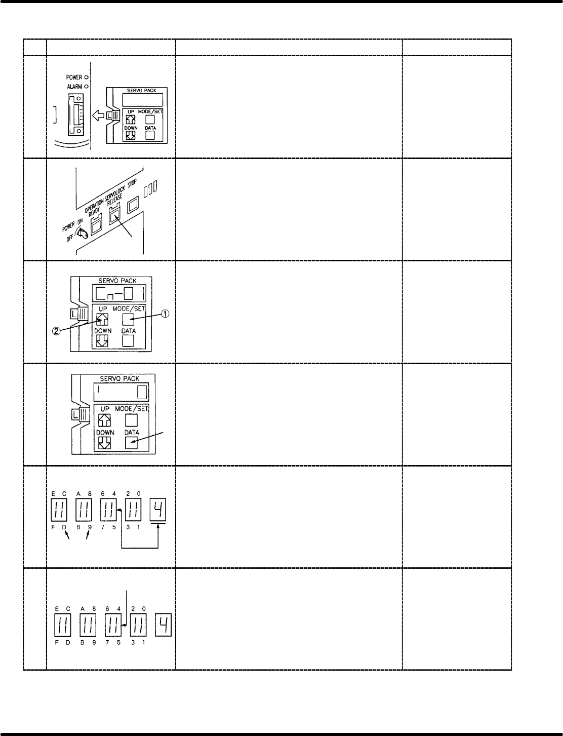
7.3.2 Inputting Bit No. (Cn−01 and Cn−02)
Display Procedure Remarks
1 Set the digital operator to the desired driver. x Set the digital
operator changes the
display to “run”.
2 Press ORG. switch in manual, 1BLOCK mode then
press servo lock switch.
x The display changes
to “b, b”.
3 Press MODE/SET to change the display to Cn−00 and
then press DATA key to specify the channel to be
input.
x Select channel
Cn−01 or Cn−02.
4 Press DATA key. x The display changes
to “ ‘ 0”.
5
Bit No.
Bit No.
to be
set
Using UP and DOWN keys, set the bit No. of the
memory switch to be set to the right end of the panel.
6
Lights up when ON
goes out when OFF
Press MODE/SET key to turn ON/OFF the memory
switch.
x The memory switch
lights up when ON and
goes out when OFF.
RH5
7.3 Digital Operator
SERVICE MANUAL
7.3−4
DA3SEC−84−310−A0
Display Procedure Remarks
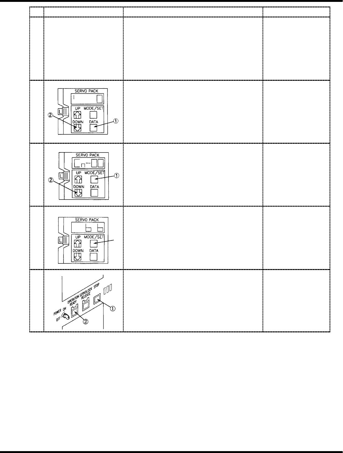
7 Repeat steps 5 and 6 as necessary.
8 Press DATA key to store data and then press DOWN
key to change the setting value at the right end of the
panel to “0”.
x Pressing DATA key
flashes the data.
9 Press DATA key to display Cn−01 or Cn−02 and then
press DOWN key to change to Cn−00.
10 Press MODE/SET key several times to change the
display to “b, b” and then press servo lock switch.
x Pressing servo lock
switch changes the
display to “run”.
11 Turn OFF the power to the machine and remove the
digital operator. Then turn the power back ON.
x After turning the power
OFF and then ON, the
setting value having
been changed will be
available.
7.3 Digital Operator
SERVICE MANUAL
RH5
7.3−5
DA3SEC−84−310−A0
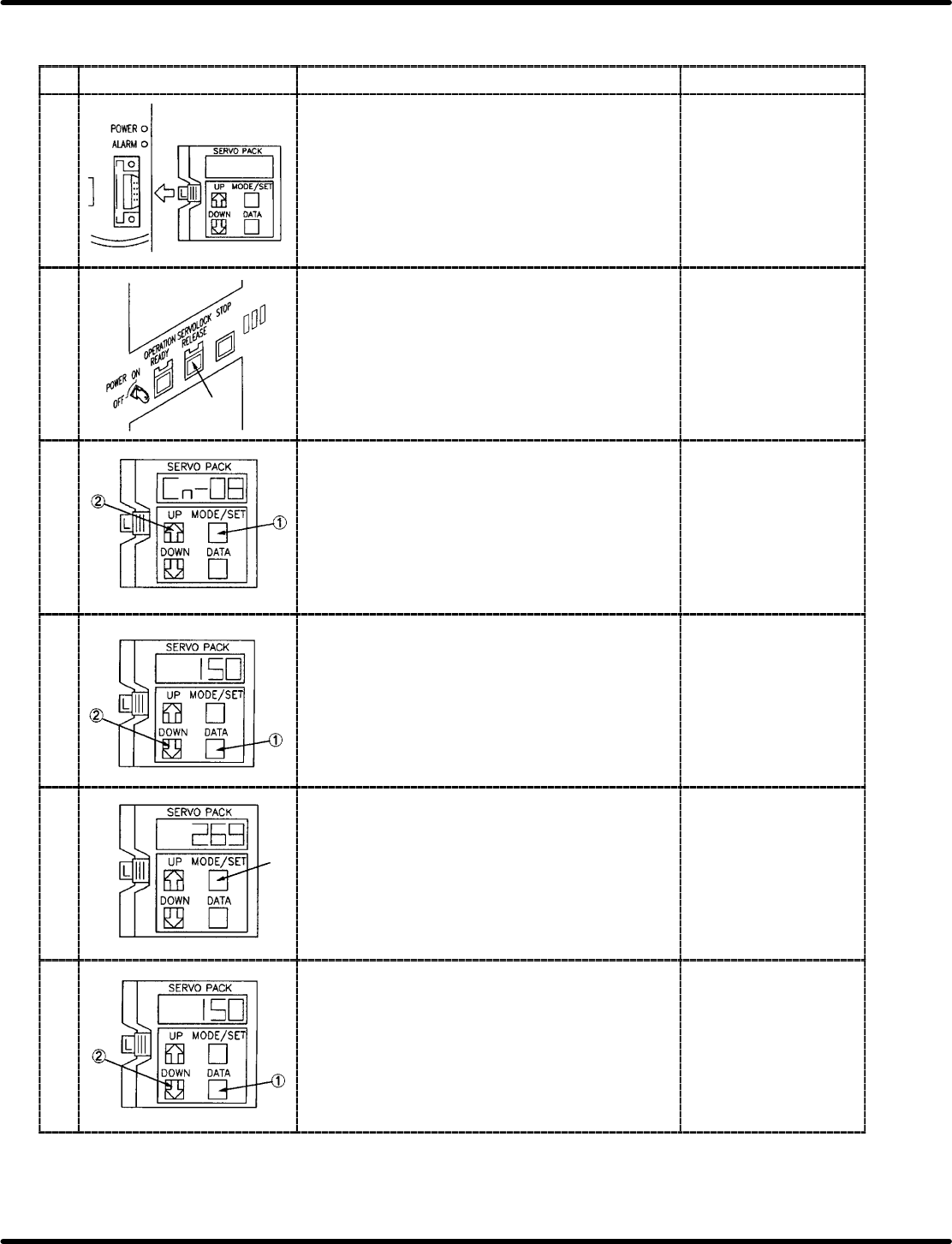
7.3.3 Changing Driver Setting Value (Cn−03 through Cn−23)
Display Procedure Remarks
1 Set the digital operator to the desired driver. x Setting the digital
operator changes the
display to “run”.
2 Press ORG. switch in manual, 1BLOCK mode then
press servo lock switch.
x The display changes
to “b, b”.
3 Press MODE/SET to change the display to Cn−00 and
then press UP key to specify the channel to be input.
x Select channel from
among Cn−03 through
Cn−23.
4 Press DATA key and input the setting value with UP
and DOWN keys.
x Refer to driver setting
list of X/Y/Z/H axis.
5 Press MODE/SET key after inputting the setting value. x Pressing MODE/SET
key flashes the data.
6 Press DATA key to display Cn−00 by DOWN key.