Q170226E01.pdf - 第108页
Hexagon headed bolt (8 mm square) Hexagon headed bolt (8 mm square) Gap gauge PC board Guide rail PC board 0.3 mm Guide rail 5.0 H 0.1 mm 5.1 XY T able Positioner and Guide Rail Check and Adjustment SERVICE MANUAL RH5 5.…
Positioner pin
Guide rail
(Slide plate)
Positioner lever
(Moving lever)
Shaft
Steel rule
Positioner pin
(Reference side)
Lever−operated
dial gauge
Parallelism:
Within 0.03 mm
Positioner pin
(Moving side)
Slide in X direction.
Positioner pin
Measuring needle
Do not set measuring
needle here.
X direction
RH5
5.1 XY Table Positioner and Guide Rail Check and Adjustment
SERVICE MANUAL
5.1−2
DA3SEC−83−8H0−A0
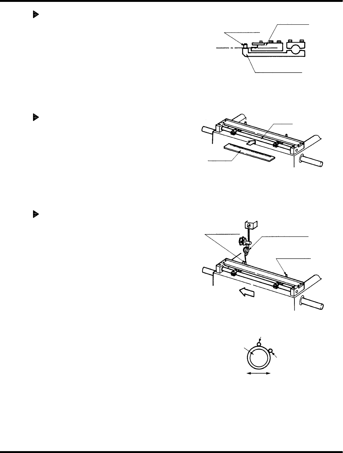
Positioner lever height check
1. With the steel rule or other scale, check the
height of the guide rail where it contacts the PC
board, and the height of the top surface of the
positioner lever are the same.
Positioner shaft straightness
check
1. Press the steel rule flat against the shaft
checking the shaft is not bent anywhere.
Measuring positioner pin
parallelism to the X−axis
1. Attach the dial gauge at the top of the base
plate on the head side.
2. Set the measuring needle on the side
surface of the positioner pin (reference
side). Bring the scale reading to “0”
(reference point).
=REFERENCE=
Set the measuring needle on the
positioner pin as shown left.
3. Slide the X−Y table in the X direction by
hand making sure that the measuring
needle contacts the side surface of the
positioner pin (moving side) and checking
parallelism is within 0.03 mm.
Hexagon headed bolt
(8 mm square)
Hexagon headed
bolt
(8 mm square)
Gap gauge
PC board
Guide rail
PC board
0.3 mm
Guide rail
5.0H0.1 mm
5.1 XY Table Positioner and Guide Rail Check and Adjustment
SERVICE MANUAL
RH5
5.1−3
DA3SEC−83−8H0−A0
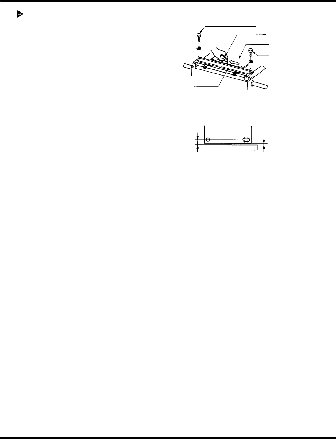
Adjusting guide rail position
1. Set a PC board and tighten the hexagon headed
bolts (x 4) enough to hold the board in place.
2. While checking with a gap gauge, move the
guide rail until the distance between the side of
the PC board and the side of the guide rail is
0.3 mm in all places.
3. After making adjustments, retighten the hexagon
headed bolts (x 2) and bolts A (x 2) so as to fix
the guide rail in place. Slide the PC board along
the rails checking to make sure it slides without
catching or incurring other irregularity.

RH5
5.1 XY Table Positioner and Guide Rail Check and Adjustment
SERVICE MANUAL
5.1−4
DA3SEC−83−8H0−A0
= MEMO =