Q170226E01.pdf - 第361页
RH5 8.7 CNC Board T able Setting SERVICE MANUAL 8.7−4 DA3SEC−85−510−B0 RH5 (LL) CNC board table setting list (X axis) 012345 6789A B C D E F 74050 74060 74070 8A 02 90 01 FA 0 0 64 00 0A 00 16 00 08 00 F4 01 0A 00 A7 00 …
8.7 CNC Board Table Setting
SERVICE MANUAL
RH5
8.7−3
DA3SEC−85−510−B0
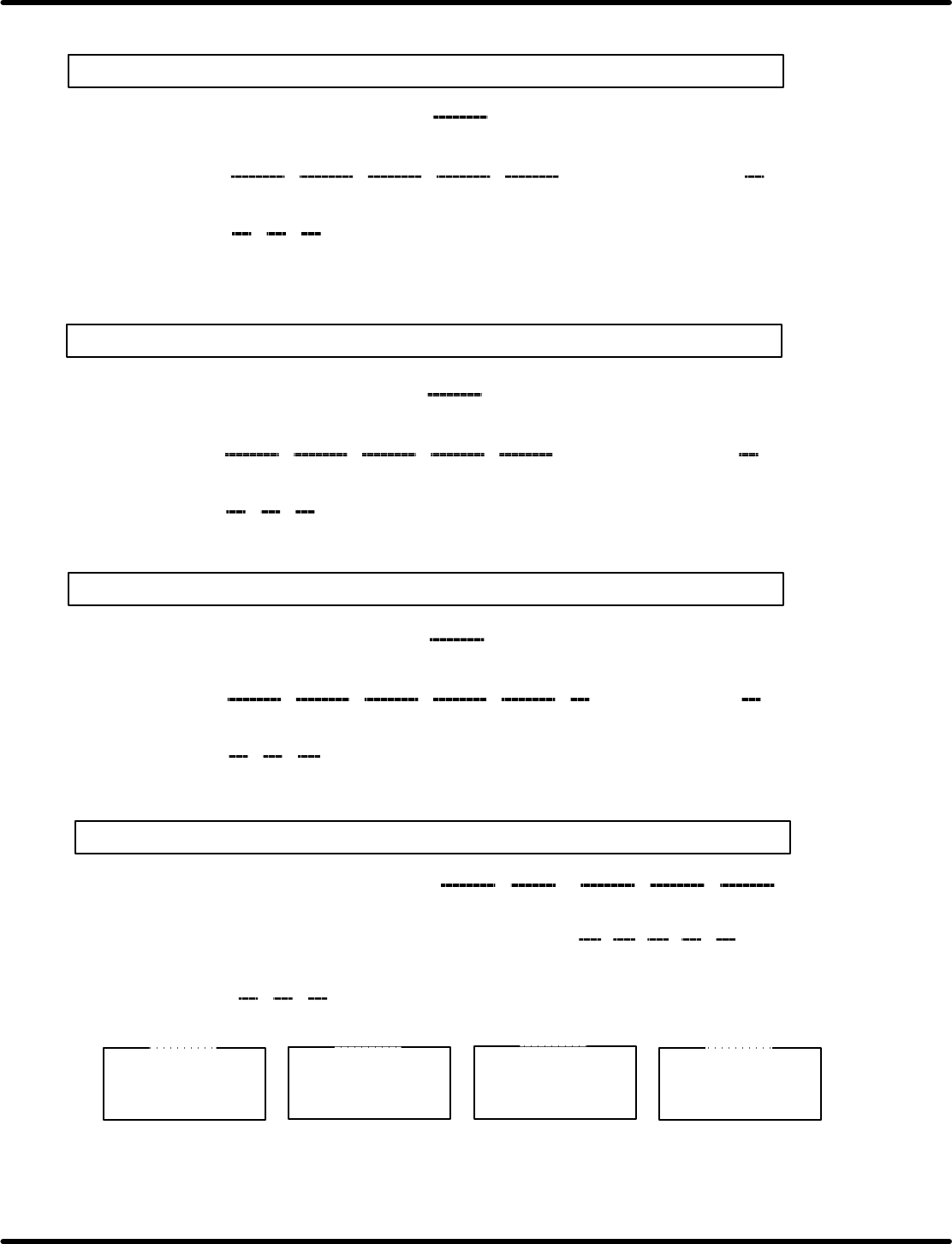
RH5(M) CNC board setting list
(X axis)
0123456789ABCDEF
74050
74060
74070
DD 02
8A 02 8A 02 64 00 0A 00
16 00
08 00 F4 01 0A 00 A7 00 2F 2D 2D 40 40 40
20
60 28 00
(Usual max. speed)
(Jog high
speed)
(Jog low
speed)
(Origin
return)
(Slow down)
(Servo lock
speed)
(Normal
acceleration)
(Jog
acceleration)
(Origin
return
acceleration)
(Servo
lock)
(Emergency
stop)
(Y axis)
0123456789ABCDEF
740D0
740E0
740F0
(Z axis)
0123456789ABCDEF
74150
74160
74170
(H axis)
0123456789ABCDEF
741D0
741E0
741F0
16 00 08 00 64 01 04 00 64 00 8C
C2 B9 74 80 64
20
40 80 00
Max. speed (0.36) (0.45) (0.6) (0.29) (0.33)
Acceleration
CA 01 6E 01130138 02 F4 01
(0.36) (0.45) (0.6) (0.29) (0.33)
DD 02 8A 02 8A 02 64 00 0A 00
16 00
08 00 F4 01 0A 00 A7 00 2F 2D 2D 40 40 40
20
60 28 01
(Usual max. speed)
(Jog high
speed)
(Jog low
speed)
(Origin
return)
(Slow down)
(Servo lock
speed)
(Normal
acceleration)
(Jog
acceleration)
(Origin
return
acceleration)
(Servo
lock)
(Emergency
stop)
FA 00 4D 01 4D 01 2C 01 2C 01
16 00
08 00 EE 00 08 00 A7 00 50 60 60 80 80 40
55
86 C8 02
(Usual max. speed)
(Jog high
speed)
(Jog low
speed)
(Origin
return)
(Slow down)
(Servo lock
speed)
(Normal
acceleration)
(Jog
acceleration)
(Origin
return
acceleration)
(Servo
lock)
(Emergency
stop)
74042 o 80
740FFE o 11
X axis
740C2 o 80
740FFE o 11
Y axis
74142 o 80
740FFE o 11
Z axis
741C2 o 80
740FFE o 11
H axis
RH5
8.7 CNC Board Table Setting
SERVICE MANUAL
8.7−4
DA3SEC−85−510−B0
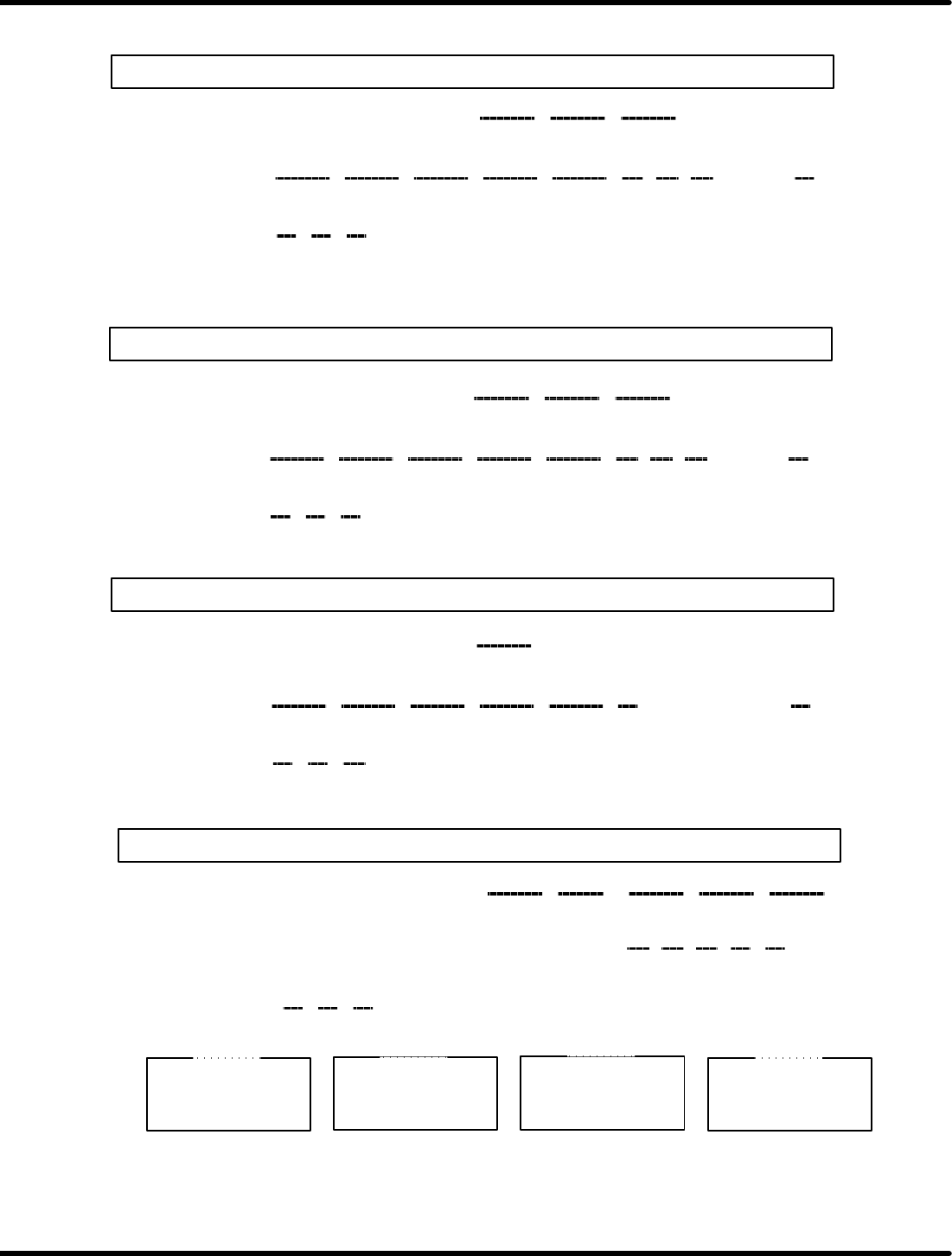
RH5 (LL) CNC board table setting list
(X axis)
0123456789ABCDEF
74050
74060
74070
8A 02
90 01 FA 00 64 00 0A 00
16 00
08 00 F4 01 0A 00 A7 00 2A 2D 3C 40 40 40
20
60 28 00
(First speed) (Second speed) (Third speed)
(Jog high
speed)
(Jog low
speed)
(Origin
return)
(Slow down)
(Servo lock
speed)
(Normal
acceleration)
(Jog
acceleration)
(Origin
return
acceleration)
(Servo
lock)
(Emergency
stop)
(Y axis)
0123456789ABCDEF
740D0
740E0
740F0
(Z axis)
0123456789ABCDEF
74150
74160
74170
(H axis)
0123456789ABCDEF
741D0
741E0
741F0
16 00 08 00 64 01 04 00 64 00 8C
C2 B9 74 80 64
20
40 80 00
Max. speed (0.36) (0.45) (0.6) (0.29) (0.33)
Acceleration
CA 01 6E 01130138 02 F4 01
(0.36) (0.45) (0.6) (0.29) (0.33)
8A 02 90 01 FA 00 64 00 0A 00
16 00
08 00 F4 01 0A 00 A7 00 2D 2D 3C 40 40 40
20
60 28 01
(Jog high
speed)
(Jog low
speed)
(Origin
return)
(Slow down)
(Servo lock
speed)
(Second
acceleration)
(Jog
acceleration)
(Origin
return
acceleration)
(Servo
lock)
(Emergency
stop)
FA 00 4D 01 4D 01 2C 01 2C 01
16 00
08 00 EE 00 08 00 A7 00 50 60 60 80 80 40
55
86 C8 02
(Usual max. speed)
(Jog high
speed)
(Jog low
speed)
(Origin
return)
(Slow down)
(Servo lock
speed)
(Second
acceleration)
(Jog
acceleration)
(Origin
return
acceleration)
(Servo
lock)
(Emergency
stop)
74042 o 80
740FFE o 11
X axis
740C2 o 80
740FFE o 11
Y axis
74142 o 80
740FFE o 11
Z axis
741C2 o 80
740FFE o 11
H axis
(First acceleration) ((Third acceleration)
(First acceleration) ((Third acceleration)
(First speed) (Second speed) (Third speed)
8.8 Monitoring I/O Signals
SERVICE MANUAL
RH5
8.8−1
DA3SEC−85−520−A0
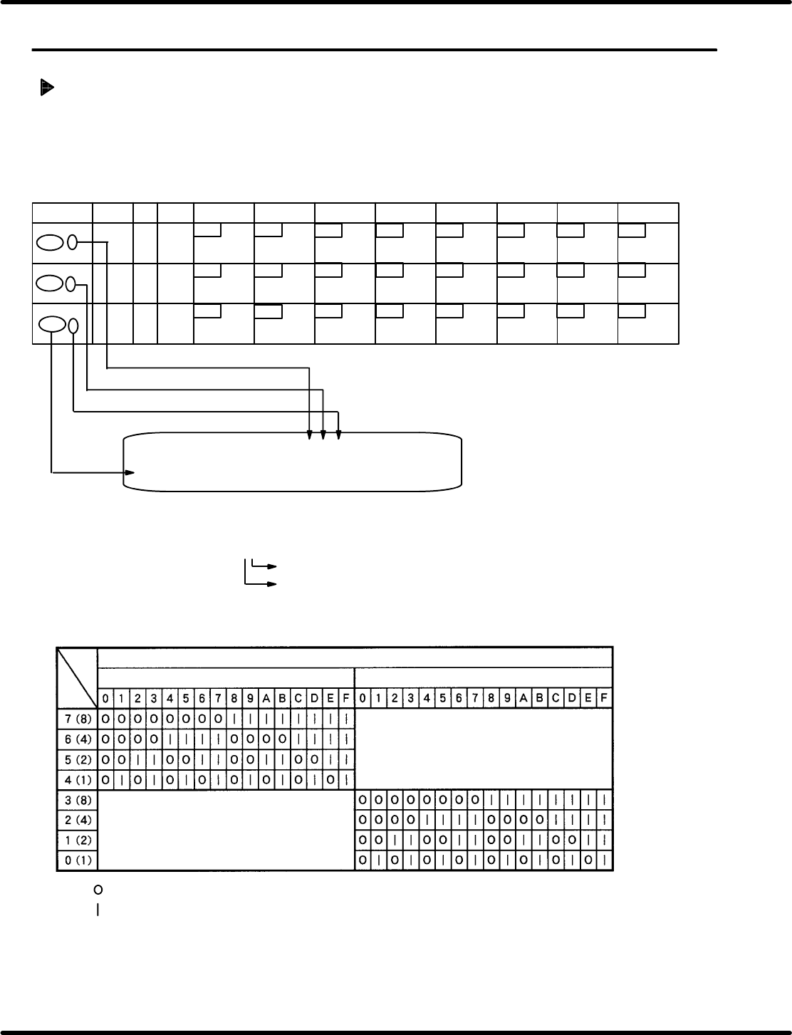
8.8 Monitoring I/O Signals
DA3SEC−85−520−A0
Sentence No.
Procedure
1. Select “F2” (MONITORING) on the operation screen.
2. Select “F3” (MEMORY) on the monitoring screen.
3. Select “F1” (CPU).
4. Call up the I/O table and monitor the signals according to the procedures below.
: Applied I/O signal for bit is OFF
: Applied I/O signal for bit is ON
Monitoring screen
ADDRESS CPU 00 01 02 03 04 05 06 07 08 09 0A 0B 0C 0D 0E 0F
70000 ** ** ** ** ** ** ** ** ** ** ** ** ** ** ** **
**: Numerics 0−9 or letters A −F
**
The one place: Display monitor of the lower bits (0−3)
Ten’s digits: Display monitor of the upper (4 − 7) bit.
Enter the desired address adding “0”
Ten’s digit
Numeric (**) on the monitor
The one place
Bit
Insertion
detection 4
Insertion
detection 3
Insertion
detection 2
Insertion
detection 1
67
00
66
65
64
63
62 61 60
ADDRESS
LABEL BLK
DEV
7 bit 6 bit
5 bit
4 bit
3 bit 2 bit 1 bit 0 bit
7000 6
7000 7
7000 8
77 76 75
00
0 100
Cutter return
Cutter forward
Mecha lock
return (Feed
lock rerun)
Mecha lock
forward (Feed
lock forward)
Parts exhaust
pre−detection
107
74
73 72 71
70
Upper cover
rear (Usually
ON)
Upper cover
front (Usually
ON)
Invert swivel
reverse limit
Invert swivel
forward limit
Invert unit
lower limit
Invert unit
upper limit
100
106 105 104 103
102
101