Q170226E01.pdf - 第114页
5.3 X−Y T able Origin and Over Limit Check and Adjustment SERVICE MANUAL RH5 5.3−3 DA3SEC−83−8KO−A0 Adjusting origin position 1. Change the CH4 (speed loop gain) of the X axis (Y axis) driver from 200 to 100. 2. T urn OF…

RH5
5.3 X−Y Table Origin and Over Limit Check and Adjustment
SERVICE MANUAL
5.3−2
DA3SEC−83−8KO−A0
=CHECK=
x Check that the display on the main control
panel indicates the origin.
x If not so, follow the procedure below.
(1) Change the CH4 from 200 to 80.
(2) Turn OFF the power and turn it back ON.
(3) Loosen the N coupling on the motor side again.
(4) Turn OFF the SERVO LOCK RELEASE and
slide the X−Y table manually up to the position
where the origin detection photonimic LED is
lit.
(5) Press ORIGIN RETURN button to return the
X−Y table to its origin.
(6) Make sure that the display on the main control
panel indicates the original position.
(7) Change the CH4 from 80 to 200.
(8) Turn OFF the power and turn it back ON.
7. Using teaching function, move the X−Y table to the
data position created in step 4.
8. Turn the hand wheel to ensure that the guide pin
comes out of the hole of the origin board.
=CHECK=
At this time, the swing accuracy of the anvil
and guide pin must be within the given range.
5.3 X−Y Table Origin and Over Limit Check and Adjustment
SERVICE MANUAL
RH5
5.3−3
DA3SEC−83−8KO−A0
Adjusting origin position
1. Change the CH4 (speed loop gain) of the X
axis (Y axis) driver from 200 to 100.
2. Turn OFF the power and turn it back ON.
3. Return the X−Y table to its origin by hand
and move it to the data position created in
step 4 in ‘Checking origin position’.
4. Disengage the N coupling.
5. Move the X−Y table manually to which the
guide pin comes out of the origin board by
turning the hand wheel.
6. Return the hand wheel to its origin and then
tighten the N coupling.
7. Change the CH4 (speed loop gain) of the X
axis (Y axis) driver from 100 to 200.
8. Turn OFF the power and turn it back ON.
9. Check the X−Y table again by following
steps 7 and 8 in ‘Checking origin position’.
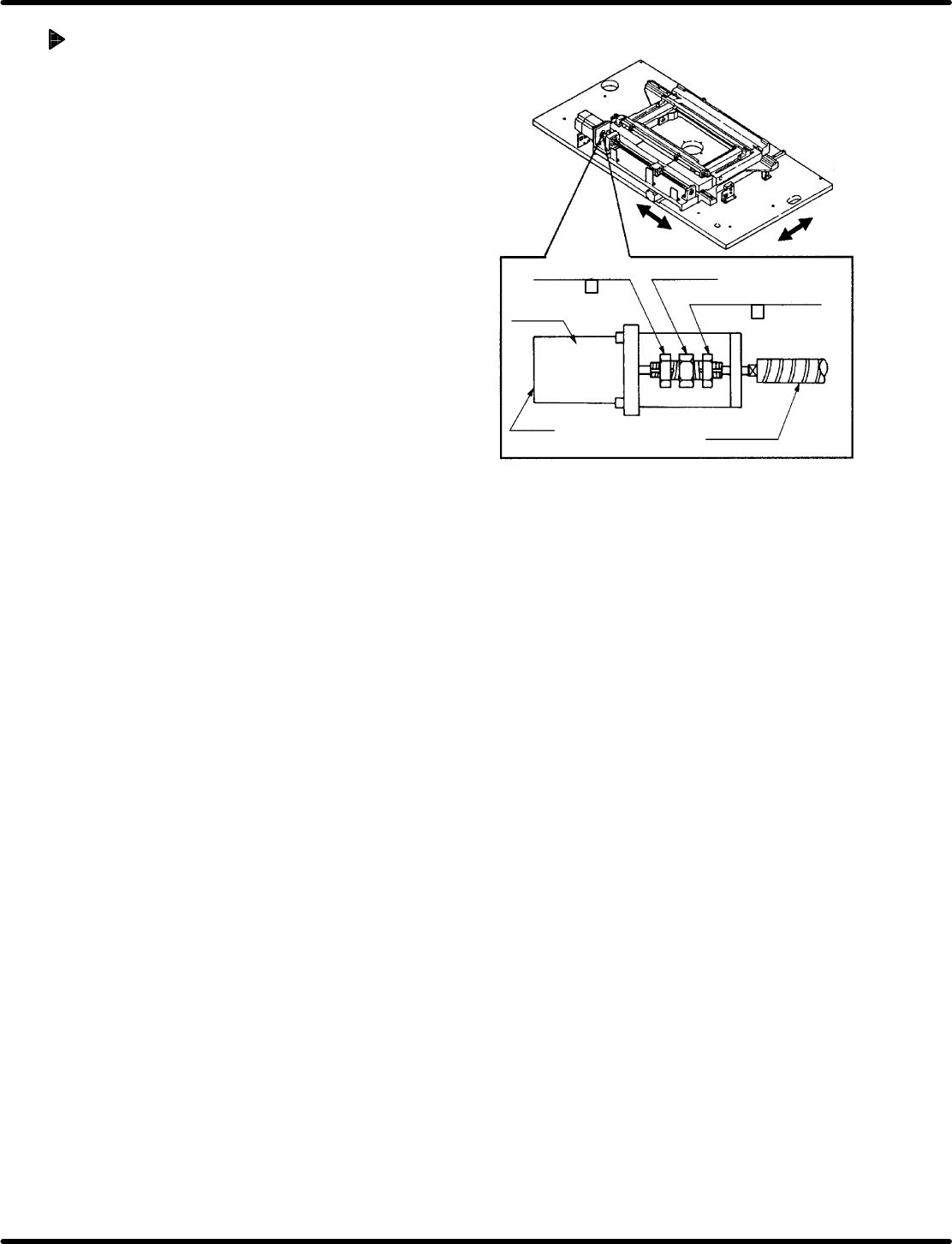
Motor side nut
(17 mm )
Ball screw side nut
(17 mm )
N coupling
Motor
LED
Ball screw
RH5
5.3 X−Y Table Origin and Over Limit Check and Adjustment
SERVICE MANUAL
5.3−4
DA3SEC−83−8KO−A0
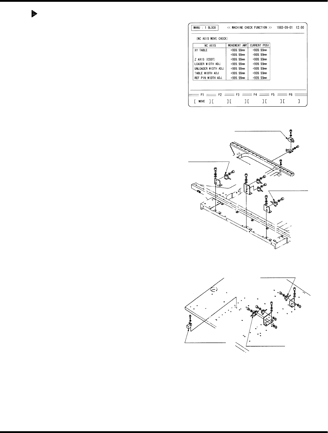
Checking/Adjusting X−Y table limit
divider
1. Select “NC AXIS MOVE CHECK” o “NC AXIS
JOG CHECK” via the main control panel. Input
the distance (numeric value) up to the X and
Y−axis limit sensors and move the axes to make
sure the sensors light up accordingly.
<M>
X−axis limit sensor:
Plus limit
(+273.40 to +273.50)
Minus limit
(−183.40 to −183.50)
Y−axis limit sensor:
Plus limit
(+1.40 to +1.50)
Minus limit
(−256.40 to −256.50)
<LL>
X−axis limit sensor:
Plus limit
(+346.40 to +346.50)
Minus limit
(−256.40 to −256.50)
Y−axis limit sensor:
Plus limit
(+1.40 to +1.50)
Minus limit
(−386.40 to −386.50)
2. If these sensors do not detect or detect early,
adjust the sensors by moving the sensor bracket.
=CHECK=
x After making adjustment, move the axes
again and check they are detected at the
sensors and that the axes move no more
than the specified distance (displayed
numeric value).
x Check that the slit plates and each
photonimic are not obstructed in any way.
X−axis safety limit
switch
X−axis + limit
sensor
X−axis − limit
sensor
Y−axis − limit
sensor
Y−axis + limit
sensor
Y−axis safety limit
switch